 English ▼



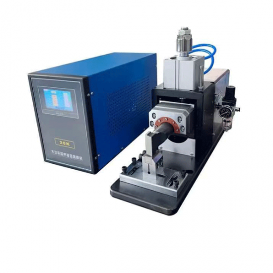
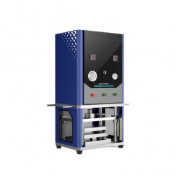
High-Power 20kHz Ultrasonic Welding Machine for Pouch Battery Packs
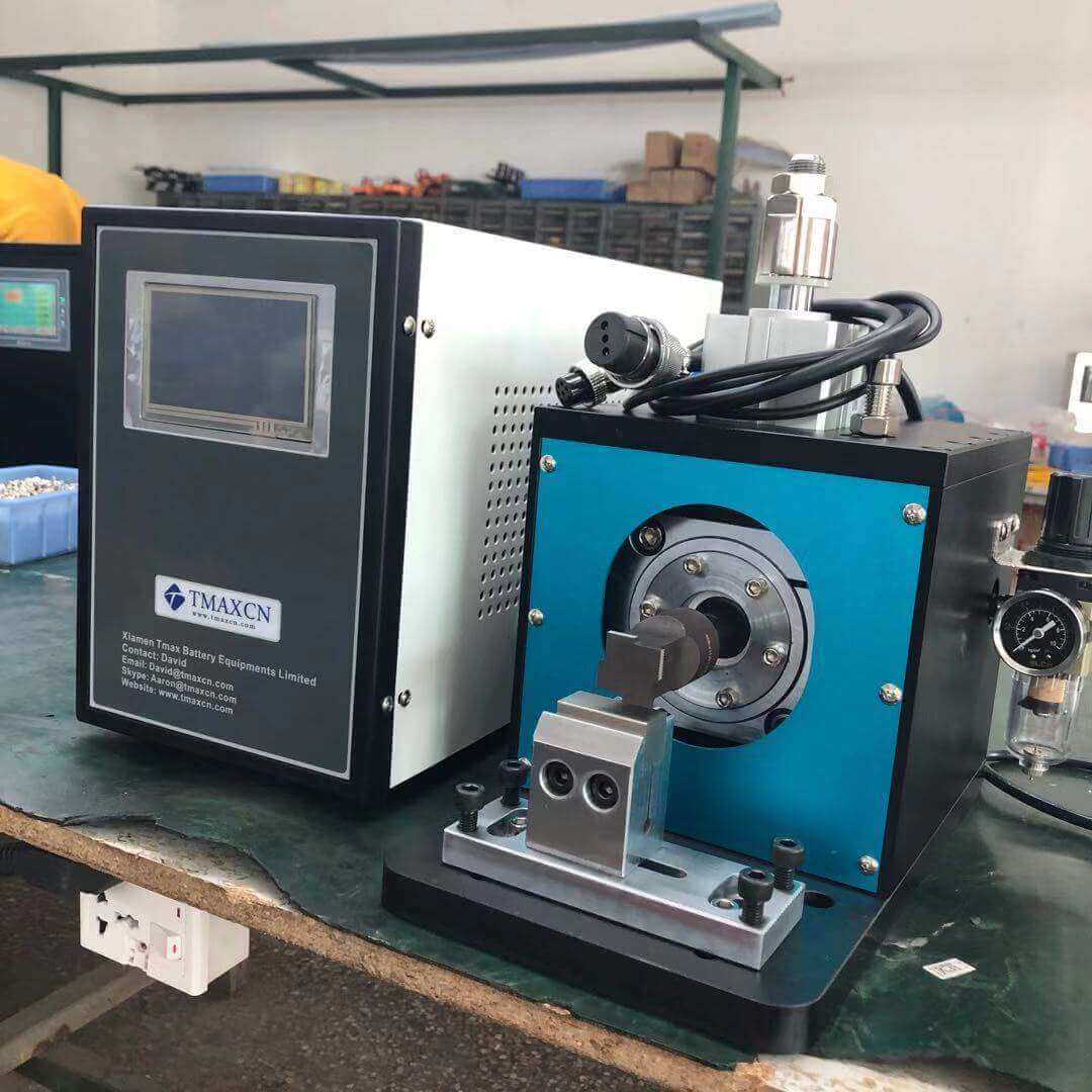
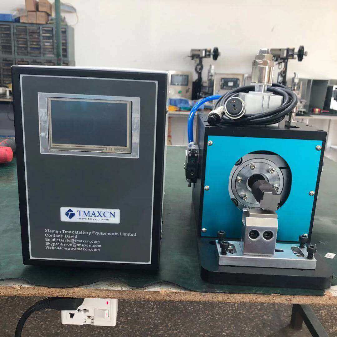
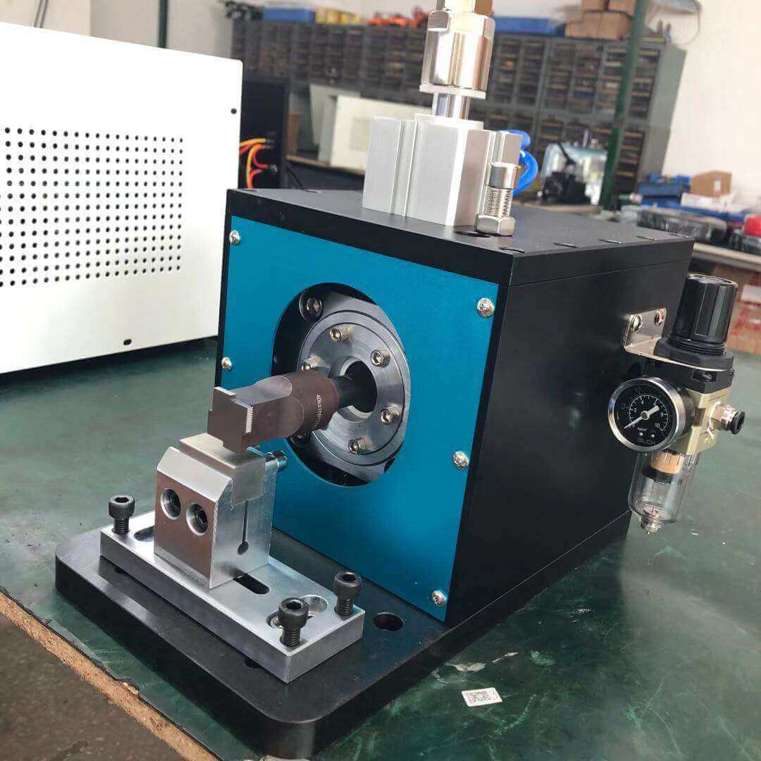
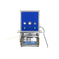
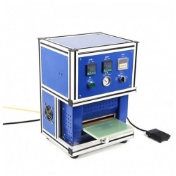
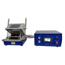
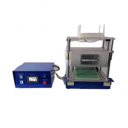
The ultrasonic welding system consists of an ultrasonic generator, transducer, welding mold (horn), pneumatic components, machine frame, and other parts.
Working Principle:
The transducer converts the high-power ultrasonic frequency oscillating signal generated by the ultrasonic generator into mechanical energy of the corresponding frequency. This energy is applied to the interface of the metal sheets to be welded. At this interface, heat is instantly generated, causing the particles in the metal lattice to activate. As a result, the molecules at the joining interface permeate into each other and form a solid weld.
I. Customer Welding Process Requirements & Corresponding Applicable Product Specifications
Item
Name
Substrate
20KHz(3000W)
1.1 Negative Electrode
1.1.1 Substrate
(electrode sheet) material
Copper foil
1.1.2 Substrate
(electrode sheet) thickness
6-12um
1.1.3 Tab (ear) material
Nickel strip
1.1.4 Tab (ear) thickness
0.01-0.1mm
1.2 Positive Electrode
1.2.1 Substrate
(electrode sheet) material
Aluminum foil
1.2.2 Substrate (ear) thickness
9-16um
1.2.3 Tab (ear) material
Aluminum
1.2.4 Tab (ear) thickness
0.01-0.1mm
1.3 Other material
1.3.1 Fe plate thickness
no more than 1mm
Cell
2.1 Cell structure
Winding or stacking
2.2 Number of layers
10–60 layers (subject to actual welding)
(4mm × 10mm weld mark)
Welding Process
3.1 Welding method
Direct welding
3.2 Weld mark area
(subject to actual welding by the customer)
Welding Horn and Anvil
4.1 Horn material
Imported high-speed steel
4.2 Horn tooth pattern shape
Upper welding head: serrated pattern
(can be modified based on actual welding process)
4.3 Horn length
(subject to customer requirements)
4.4 Usable welding surface of horn
2–4 usable surfaces
4.5 Horn service life
Negative electrode > 300,000 times,
Positive electrode > 400,000 times
4.6 Anvil material
High-speed steel
4.7 Anvil tooth pattern shape
Mesh pattern
(can be modified based on actual welding process)
4.8 Usable positions of anvil
1 piece
4.9 Anvil service life
Approx.: Negative electrode > 300,000 times,
Positive electrode > 400,000 times
4.10 Stroke of the horn
30mm
Transducer
5.1 Transducer frequency
20KHz±0.15KHz
5.2 Transducer power
3600W (peak)
Ultrasonic Generator
6.1 Ultrasonic power
≤3600W (peak)
6.2 Frequency tracking range
20KHz±1KHz
6.3 Frequency tracking method
Automatic real-time frequency tracking
6.4 Welding functions
Supports time and energy control modes
6.5 Pressure adjustment range
0MPa–1MPa, adjustable
6.6 Time adjustment range
0–60s, adjustable
6.7 Welding time
≤0.5S
6.8 Amplitude adjustment range
10%~100%
6.9 Quality control functions
Equipped with frequency, power, energy, and amplitude upper/lower limit alarm and shutdown functions.
6.10 Input voltage
220V ±10% AC (50/60Hz, single phase)
6.11 Welding Data Storage
The machine is equipped with memory to record and store welding data history.
6.12 Adjustable Welding Energy
Welding energy can be adjusted according to process requirements.
6.13 Welding Power Display
The machine can display the power of each welding operation.
Quality
7.1 Welding quality
Inter-layer fusion, firm welding, no missed or false welds, no cracks in the weld area or surrounding regions
7.2 Yield rate
≥99.5% (with consistent incoming materials)
7.3 Equipment Designed Service Life
10 years
7.4 Standard Accessories Included
One set of tools included.
7.5 Warranty
1-year warranty for the main unit, including welding head; consumables excluded.
II. Product Information
A. Utilizes advanced constant current and constant voltage circuit technology; ultrasonic amplitude is continuously adjustable.
B. Equipped with intelligent ICS chassis control system with secondary ultrasonic function; system performs self-diagnosis at startup, segmented intelligent amplitude output, and real-time automatic tracking.
C. The welding head’s mechanical structure adopts German-style X-axis guide rail design for extremely high precision.
D. Protection System:
1) Voltage protection system (supply voltage range: 220V–250V); output power and working frequency remain unaffected during automatic voltage stabilization.
2) Overload protection system
3) Overcurrent protection
4) Automatic compensation for unstable supply frequency
5) Feedback system for welding overload protection
III. General equipment configuration and standards
1) Noise Level:Measured at 1 meter from the equipment’s outer wall. Noise level during normal operation: <75dB.
2) Operating Environment:
3) Ambient Temperature: 20±5°C
4) Relative Humidity: 60% RH
5) Site must be free from corrosive gases/liquids and explosive gases.
6) Factory load-bearing capacity: ≤800kg/m2.
IV. Equipment Dimensions
1) Generator Dimensions (L × W × H): 550mm × 300mm × 550mm
2) Welding Head Dimensions (L × W × H): 480mm × 200mm × 380mm
The ultrasonic welding system consists of an ultrasonic generator, transducer, welding mold (horn), pneumatic components, machine frame, and other parts.
Working Principle:
The transducer converts the high-power ultrasonic frequency oscillating signal generated by the ultrasonic generator into mechanical energy of the corresponding frequency. This energy is applied to the interface of the metal sheets to be welded. At this interface, heat is instantly generated, causing the particles in the metal lattice to activate. As a result, the molecules at the joining interface permeate into each other and form a solid weld.
I. Customer Welding Process Requirements & Corresponding Applicable Product Specifications
|
Item |
Name |
|
Substrate |
20KHz(3000W) |
|
1.1 Negative Electrode |
|
|
1.1.1 Substrate (electrode sheet) material |
Copper foil |
|
1.1.2 Substrate (electrode sheet) thickness |
6-12um |
|
1.1.3 Tab (ear) material |
Nickel strip |
|
1.1.4 Tab (ear) thickness |
0.01-0.1mm |
|
1.2 Positive Electrode |
|
|
1.2.1 Substrate (electrode sheet) material |
Aluminum foil |
|
1.2.2 Substrate (ear) thickness |
9-16um |
|
1.2.3 Tab (ear) material |
Aluminum |
|
1.2.4 Tab (ear) thickness |
0.01-0.1mm |
|
1.3 Other material |
|
|
1.3.1 Fe plate thickness |
no more than 1mm |
|
Cell |
|
|
2.1 Cell structure |
Winding or stacking |
|
2.2 Number of layers |
10–60 layers (subject to actual welding) (4mm × 10mm weld mark) |
|
Welding Process |
|
|
3.1 Welding method |
Direct welding |
|
3.2 Weld mark area |
(subject to actual welding by the customer) |
|
Welding Horn and Anvil |
|
|
4.1 Horn material |
Imported high-speed steel |
|
4.2 Horn tooth pattern shape |
Upper welding head: serrated pattern (can be modified based on actual welding process) |
|
4.3 Horn length |
(subject to customer requirements) |
|
4.4 Usable welding surface of horn |
2–4 usable surfaces |
|
4.5 Horn service life |
Negative electrode > 300,000 times, Positive electrode > 400,000 times |
|
4.6 Anvil material |
High-speed steel |
|
4.7 Anvil tooth pattern shape |
Mesh pattern (can be modified based on actual welding process) |
|
4.8 Usable positions of anvil |
1 piece |
|
4.9 Anvil service life |
Approx.: Negative electrode > 300,000 times, Positive electrode > 400,000 times |
|
4.10 Stroke of the horn |
30mm |
|
Transducer |
|
|
5.1 Transducer frequency |
20KHz±0.15KHz |
|
5.2 Transducer power |
3600W (peak) |
|
Ultrasonic Generator |
|
|
6.1 Ultrasonic power |
≤3600W (peak) |
|
6.2 Frequency tracking range |
20KHz±1KHz |
|
6.3 Frequency tracking method |
Automatic real-time frequency tracking |
|
6.4 Welding functions |
Supports time and energy control modes |
|
6.5 Pressure adjustment range |
0MPa–1MPa, adjustable |
|
6.6 Time adjustment range |
0–60s, adjustable |
|
6.7 Welding time |
≤0.5S |
|
6.8 Amplitude adjustment range |
10%~100% |
|
6.9 Quality control functions |
Equipped with frequency, power, energy, and amplitude upper/lower limit alarm and shutdown functions. |
|
6.10 Input voltage |
220V ±10% AC (50/60Hz, single phase) |
|
6.11 Welding Data Storage |
The machine is equipped with memory to record and store welding data history. |
|
6.12 Adjustable Welding Energy |
Welding energy can be adjusted according to process requirements. |
|
6.13 Welding Power Display |
The machine can display the power of each welding operation. |
|
Quality |
|
|
7.1 Welding quality |
Inter-layer fusion, firm welding, no missed or false welds, no cracks in the weld area or surrounding regions |
|
7.2 Yield rate |
≥99.5% (with consistent incoming materials) |
|
7.3 Equipment Designed Service Life |
10 years |
|
7.4 Standard Accessories Included |
One set of tools included. |
|
7.5 Warranty |
1-year warranty for the main unit, including welding head; consumables excluded. |
II. Product Information
A. Utilizes advanced constant current and constant voltage circuit technology; ultrasonic amplitude is continuously adjustable.
B. Equipped with intelligent ICS chassis control system with secondary ultrasonic function; system performs self-diagnosis at startup, segmented intelligent amplitude output, and real-time automatic tracking.
C. The welding head’s mechanical structure adopts German-style X-axis guide rail design for extremely high precision.
D. Protection System:
1) Voltage protection system (supply voltage range: 220V–250V); output power and working frequency remain unaffected during automatic voltage stabilization.
2) Overload protection system
3) Overcurrent protection
4) Automatic compensation for unstable supply frequency
5) Feedback system for welding overload protection
III. General equipment configuration and standards
1) Noise Level:Measured at 1 meter from the equipment’s outer wall. Noise level during normal operation: <75dB.
2) Operating Environment:
3) Ambient Temperature: 20±5°C
4) Relative Humidity: 60% RH
5) Site must be free from corrosive gases/liquids and explosive gases.
6) Factory load-bearing capacity: ≤800kg/m2.
IV. Equipment Dimensions
1) Generator Dimensions (L × W × H): 550mm × 300mm × 550mm
2) Welding Head Dimensions (L × W × H): 480mm × 200mm × 380mm







 Subscribe to us
 ONLINE
 +86 13174506016

 18659217588