- Language:
 English ▼
English ▼
ItemNo :
LITH-GKZYJ-02-1000MOQ :
1Delivery Time:
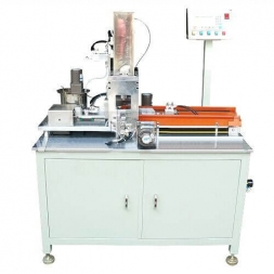
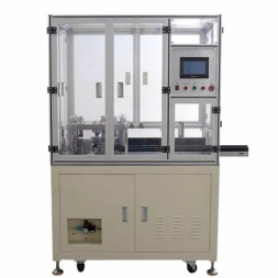
5 daysSemi-Automatic Electrolyte Filling Machine for Cylindrical Cells
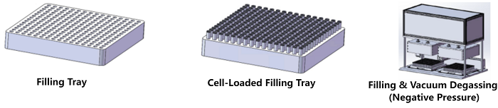
1.1 This equipment is mainly used on a semi-automatic assembly line for cylindrical cells inside a glove box, for electrolyte filling and pressurized degassing (vacuum pressurization).
1.2 Process flow: Pre-fill manual weighing → Manual loading (place cells onto tray) → Electrolyte filling → Pressurized degassing → Manual removal of cylindrical cells → Post-fill manual weighing.
|
Category |
Process Technical Parameters |
|
Equipment capacity |
Single machine ≥ 10 PPM (under continuous manual feeding; continuous production 2 h) |
|
Filling accuracy (per shot) |
±0.1 g |
|
Pump delivery precision |
≤ 3‰, digital intelligent adjustable pump |
|
Equipment utilization |
98% (only failures caused by this machine) |
|
First-pass yield |
99.4% (only defects caused by this machine) |
|
Compatibility |
Changeover by replacing tray and filling cup set (supplied for 21700) |
|
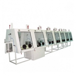
Glove box sections |
Three sections |
|
Gloves |
Three pairs (front & rear) |
|
Glove box material |
SUS304 |
|
Transition chamber size |
400 × 400 × 400 mm |
|
Top air inlet/outlet |
Ø110 |
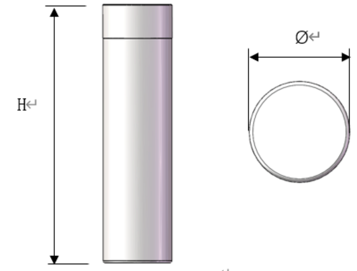
Cylindrical cell size range: (as per customer drawing/specification).
|
Code |
H (Height, mm) |
Ø (OD, mm) |
|
Min |
65 |
18 |
|
Max |
70 |
21 |
|
No. |
Mechanism |
Qty. |
Description |
|
1 |
Tray |
1 |
1) Tray is fixed inside the equipment. 2) For changeover, only the cup set and tray need replacement. |
|
2 |
Filling |
1 |
1) After filling, no dripping from the filling needle is allowed. 2) Storage-tank pressure is automatically controlled; the system de-gasses the electrolyte and has low-level detection with automatic replenishment. 3) Main filling line includes bubble-purge function. 4) A stainless-steel filter ≥ 200 mesh is installed before the pump (in the filling tank). 5) Filling-needle height is settable. |
|
3 |
Degassing |
1 |
1) Degassing time can be set 10–30 min as needed. 2) Isobaric (equal-pressure) degassing: evacuate the degassing chamber and the cells; cycle count configurable per process. 3) Vacuum regulation range: up to −95 kPa. 4) Pressure control accuracy ±5%; positive/negative pressure drop ≤ 2 kPa/min. |
|
4 |
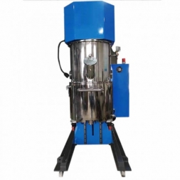
Electrolyte tank system |
1 |
1) Two tanks: one for motor-assisted degassing/settling, one for filling. 2) Tanks placed in a sealed dry environment. 3) Automatic electrolyte feeding. 4) Four dedicated drip trays for liquid collection. 5) After liquid discharge, residual electrolyte in pipelines and buffer tank ≤ 500 g. Each filling tank has two level-sensing points; software can select/switch the detection position to ensure residual < 500 g in tank. |
|
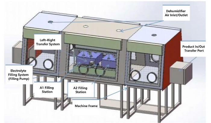
5 |
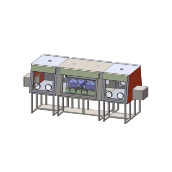
Glove box |
1 |
1) Cylinder-actuated transition-chamber door. 2) Transparent PETG viewing windows. 3) Transition chamber ≈ 400 × 400 × 400 mm. 4) Each section top requires one Ø110 inlet and one Ø110 outlet. 5) Each section top reserves a 100 × 100 mm square port for internal electrical installation; fastened by screws and sealed with sealant. 6) Six lamp holders in total. 7) Main frame: 40-mm SUS square-tube welded structure. 8) Box & base plate: 2 mm SUS304 welded; outer surface brushed finish. |
|
6 |
Control system |
1 |
Industrial PC + PLC as the control core for all machine motions. |
1. Structural materials prioritized as aluminum and stainless steel or plated anti-corrosion to ensure no rust/oxidation.
2. Quick tray removal for maintenance (remove one machine tray within 35 min).
3. Workbench shall have electrolyte drainage grooves and a collection tank; cable ducts on the workbench shall be aluminum.
4. After bubbles occur, electrolyte discharge is convenient, routed to the collection tank.
5. Electrical cabinet made of stainless steel, polished matte; stainless-steel screws and nuts.
6. Main machine frame uses square tube with baked-paint finish; other parts consider anti-corrosion and wear-resistance; ensure no rust/oxidation.
7. Neat routing for cables and pipelines; overall coordination; drag chains used for long-travel motion.
8. The machine is mounted under an upper rack; the filling area is sealed. The rack glass uses anti-corrosion PC transparent panels. The top is connected to the plant exhaust to quickly extract electrolyte/DMC odors and keep humidity inside/outside consistent.
9. HMI modules shall be clear and user-friendly for operators.
|
No. |
Name |
Brand |
Notes |
|
1 |
Pneumatic components |
AIRTAC / Domestic |
|
|
2 |
Linear guide |
HIWIN |
|
|
3 |
Ball screw |
HIWIN |
|
|
4 |
Linear bearing |
YTP / HRB |
|
|
5 |
Servo motor / Driver |
Delta |
|
|
6 |
PLC |
Panasonic / Inovance / XINJE |
|
|
7 |
Touchscreen |
Weintek / XianKong |
|
|
8 |
Stepper motor |
Jianghua Motor |
|
|
9 |
AC motor |
Jianghua Motor |
|
|
10 |
Temperature-control system |
XINJE |
|
|
11 |
Intelligent electrolyte pump |
Dongguan Jiyanda (touchscreen adjustment, ceramic pump core) |
|
|
Category |
Specification |
|
Overall dimensions |
≈ L 3.8 m × W 1.8 m × H 1.8 m |
|
Weight |
2.5 T |
|
Floor load requirement |
> 500 kg/m² |
|
Power supply (by Buyer) |
Two-phase AC220 V ±10%, 50 Hz; Power: 7 kW |
|
Compressed air (by Buyer) |
0.5–0.7 MPa (5–7 kgf/cm²); 10 L/s; dried, filtered, regulated |
|
Vacuum (by Buyer) |
≤ −0.095 MPa; 40 L/s |
|
Relative humidity (by Buyer) |
0–90% RH |
|
Magnetic field & vibration (by Buyer) |
No magnetic field affecting the device; no shock or vibration |
|
No. |
Name |
Specification / Model |
Qty |
Manufacturer |
|
1 |
Cup-set O-ring |
Standard 16 × 1.5 mm O-ring |
200 |
— |
|
2 |
Pump O-ring |
Standard 22 × 2 mm O-ring |
20 |
— |
|
3 |
Filling-needle check valve |
Non-standard custom |
2 |
TMAX |
|
4 |
Hex wrench set |
1.5–10 mm |
1 set |
TGK |
|
5 |
Open-end wrench set |
6–22 mm |
1 set |
— |
|
6 |
Adjustable wrench |
Adjustable wrench |
1 pc |
— |
|
7 |
Screwdrivers |
101 flathead; 101 Phillips |
1 each |
— |
|
8 |
Toolbox |
— |
1 pc |
— |

![]()
![]()

![]()
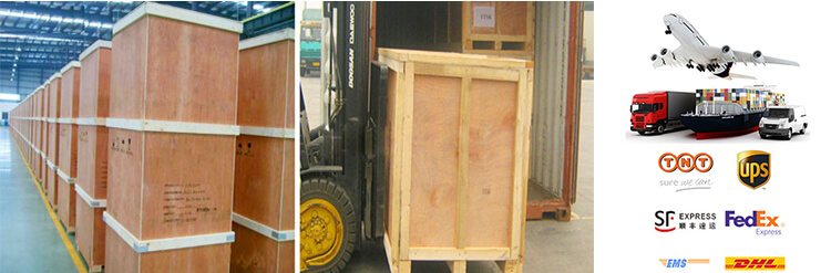
1 Standard exported package: Internal anticollision protection, external export wooden box packaging.
2 Shipping by express, by air, by sea according to customers' requirements to find the most suitable way.
3 Responsible for the damage during the shipping process, will change the damaged part for you for free.
DELIVERY TIME:15-20 days after confirming the order, detail delivery date should be decided according to
production season and order quantity.

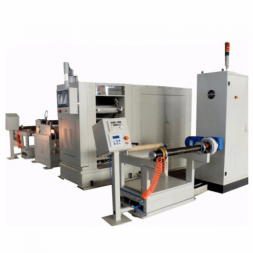
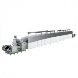
Precision Extrusion Single Side Slot Die Coating Machine For Battery Production
 Subscribe to us
 ONLINE
 +86 13174506016
 Louis@lithmachine.com
 +86 18559646958
 18659217588