- Language:
 English ▼
English ▼
ItemNo :
LITH-ZDRK18650MOQ :
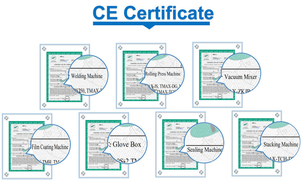
1Compliance:
CEWarranty:
2 yearsDelivery Time:
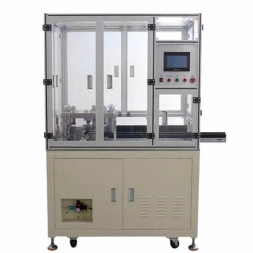
5 daysAutomatic 18650 Cylindrical Cell Lithium-ion Battery Shell Insertion Machine
1. Mechanical Design Technical Requirements
l Equipment Name: Cylindrical Lithium-ion Battery Shell Insertion Machine
l Applicable Product: 18650 series (anode with single or double tabs)
l Technical Performance
a. Cycle Time: 60 PPM
b. Equipment Availability (OEE): >90% (Normal production time ÷ (Downtime + Normal production time) × 100%)
c. Product Yield: >99%
l Material Requirements
a. Machine Frame: Recommended to use square tube welded structure, with magnetic devices installed inside the door panels.
b. Main Mechanical Structure: S45C steel.
l Equipment Dimensions (mm)
a. Length: 2500
b. Width: 2000 (including the material pick-up section)
c. Height: 1900
d. Table Height (including main base plate): 680–720
e. After the 3D model is completed, it must be reviewed and finalized with Party A.
2. Electrical Control Technical Requirements
1. Operating Environment: Temperature -10°C to 45°C; relative humidity <95% acceptable.
2. Power Supply: Single-phase 220VAC, 50Hz.
3. Compressed Air: Pressure >0.5 MPa; flow rate 180 L/min.
This equipment is an automatic shell insertion device for 18650 cylindrical lithium-ion cells (anode with single or double tabs).
l The cell reel feeding mechanism is docked with the upstream winding machine.
l The wound core is automatically picked from the conveyor line by a manipulator for automatic loading.
l The steel can is manually placed into the material tray for automatic distribution.
l The equipment automatically measures the outer diameter of the wound core and rejects defective ones.
l Automatic tab alignment for the cell tabs.
l Automatic punching and insertion of anode insulation disks.
l Automatic tab bending.
l Automatic shell insertion of the wound core.
The cell is loaded into a carrier and fed by a belt. The wound core is indexed in sequence by a cam indexer for inspection. Shell insertion is performed in two steps, both monitored by pressure sensors.
After insertion, the cells are conveyed by two belt conveyors. The manipulator automatically picks and places for loading and unloading. All operations are automatically completed, and finished products flow into the next production process.
A. Mechanical Structure Design Plan
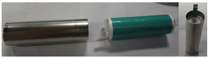
- Product Components:
|
Component |
Quantity |
|
Steel Can |
1 pcs |
|
Insulation Disk |
1 pcs |
|
Cell |
1 pcs |
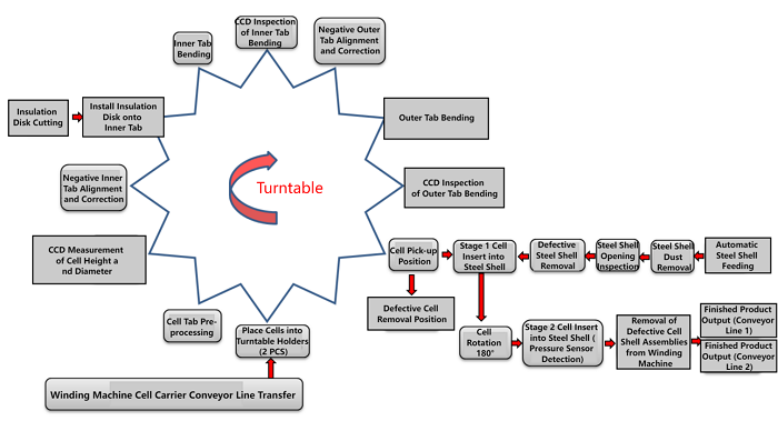
- Automatic Station Workflow:
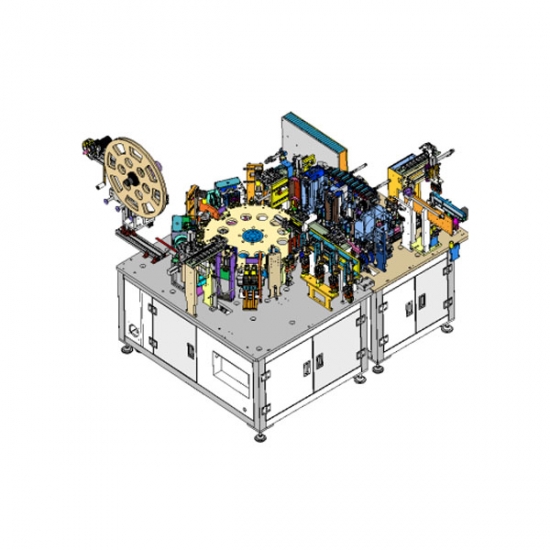
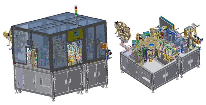
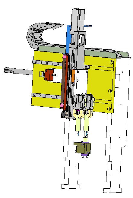
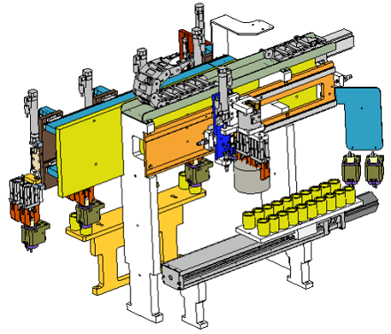
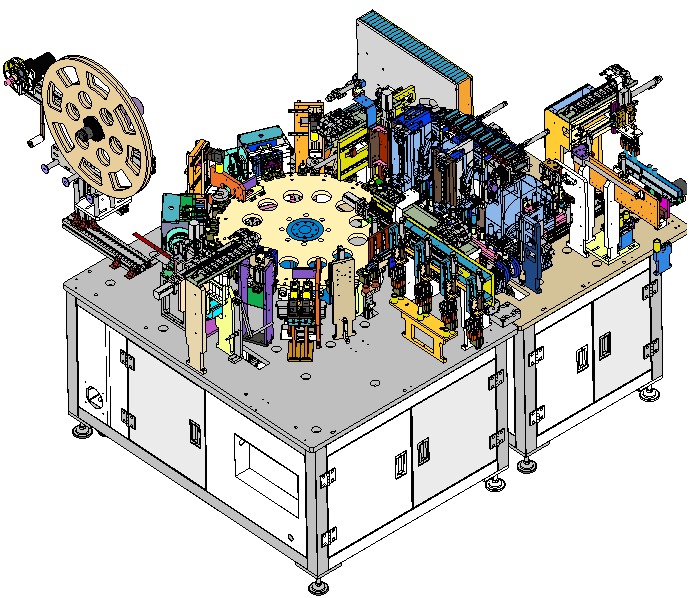
- Automatic Assembly Machine Model Diagram:
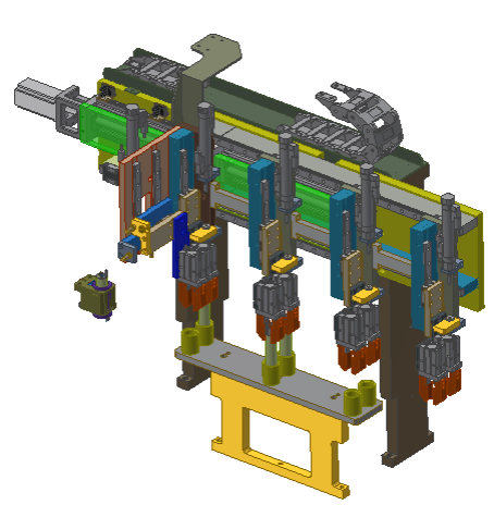
- Loading to Rotary Table Model Diagram:
The cell is clamped by grippers, 2 pcs each time, and transferred to the rotary table by a servo-driven transfer mechanism.
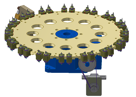
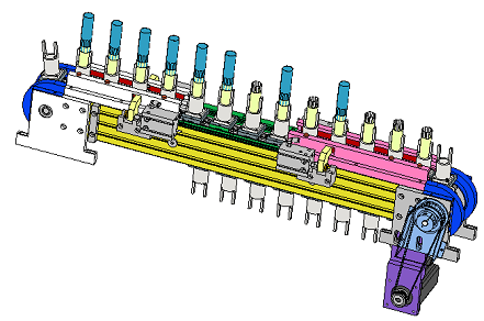
- Rotary Table + Fixture Seat Mechanism Model Diagram:
The cell fixture seats are fixed on the rotary table. Each station corresponds to two fixture seats, with a total of 16 stations.
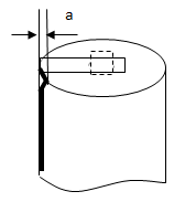
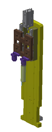
- Outer Tab Pre-forming Mechanism Model Diagram:
The outer tabs are opened outward from an inward-inclined position through the tab forming mechanism.
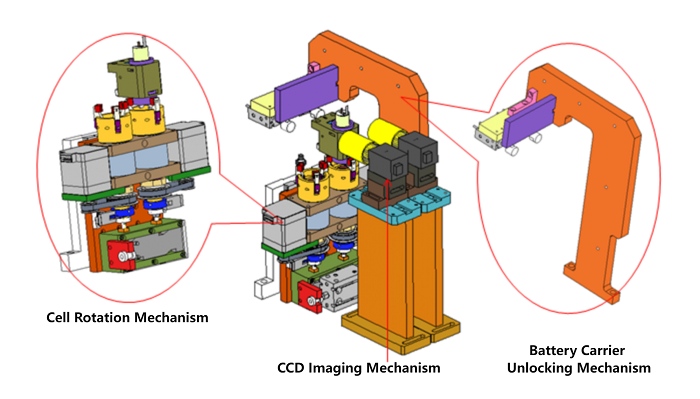
- Inner Tab CCD Imaging Mechanism Model Diagram:
The cell fixture unlocking mechanism releases the cell, then the cell is rotated by the rotation mechanism. The CCD continuously captures images, and when the inner tab is detected to be in the programmed assembly position, the rotation stops.
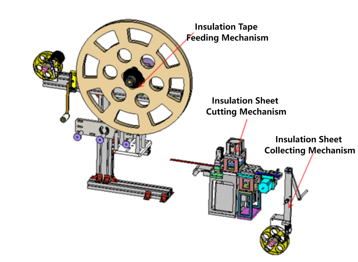
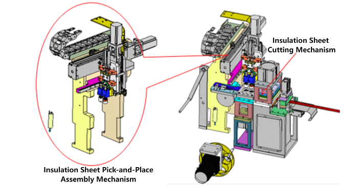
- Insulation Disk Loading + Cutting & Forming Mechanism Model Diagram:
The roll-fed insulation disk is loaded from the tray, then cut and formed by the cutting mechanism. Waste material is collected by a reel take-up mechanism.
- Insulation Disk Pick-and-Place onto Cell Mechanism Model Diagram:
After cutting, the insulation disk is picked up by a hollow suction unit (2 pcs each time), then placed onto the cell by a servo transfer mechanism.
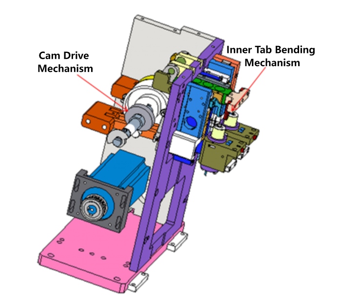
- Inner Tab Cam Bending Mechanism Model Diagram:
The inner tab bending mechanism is driven by a cam transmission.
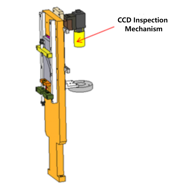
- Inner Tab Bending CCD Inspection Mechanism Model Diagram:
CCD inspects the rebound height of the bent inner tab to ensure the bending is acceptable.
- Outer Tab CCD Imaging Mechanism Model Diagram:
The cell fixture unlocking mechanism releases the cell, then the cell is rotated by the rotation mechanism. The CCD continuously captures images, and when the outer tab is detected to be in the programmed assembly position, the rotation stops.

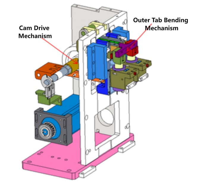
- Outer Tab Bending CCD Inspection Mechanism Model Diagram:
The outer tab bending mechanism is driven by a cam transmission.
- Cell Transfer Out of Rotary Table Mechanism Model Diagram:
Qualified assembled cells are transferred out of the rotary table by grippers.
- Cell Chain Conveyor Mechanism Model Diagram:
Qualified cells are transported by chain carriers.
- Cell Rejection Mechanism Model Diagram:
Cells identified as defective during previous inspection steps are finally rejected by the manipulator and placed on a servo carrier, to be removed manually.
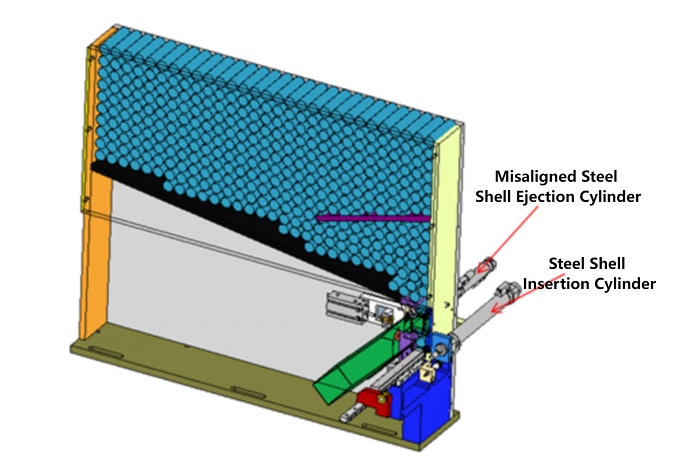
- Steel Can Distribution Mechanism Model Diagram:
Steel cans are placed into the storage bin. Misoriented cans are rejected by a cylinder; qualified cans are pushed into the chain carrier by a cylinder.
- Steel Can Chain Conveyor + Defective Rejection Mechanism Model Diagram:
Steel cans are conveyed by a chain conveyor. When reversed cans are detected, they are rejected by the defective discharge mechanism. Two steel cans are positioned for cell assembly.
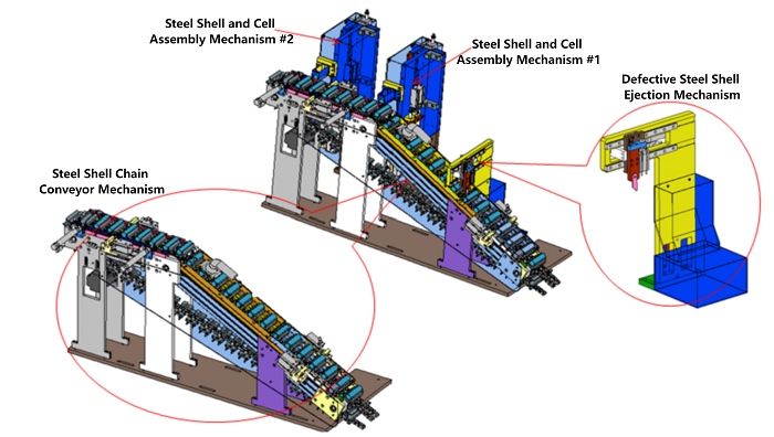
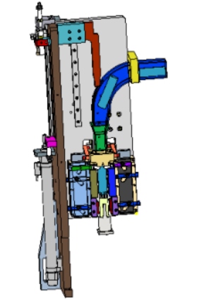
- Steel Can and Cell Assembly Mechanism Model Diagram:
The cell is positioned on the chain carrier, and the steel can is assembled with the cell in an inverted orientation.
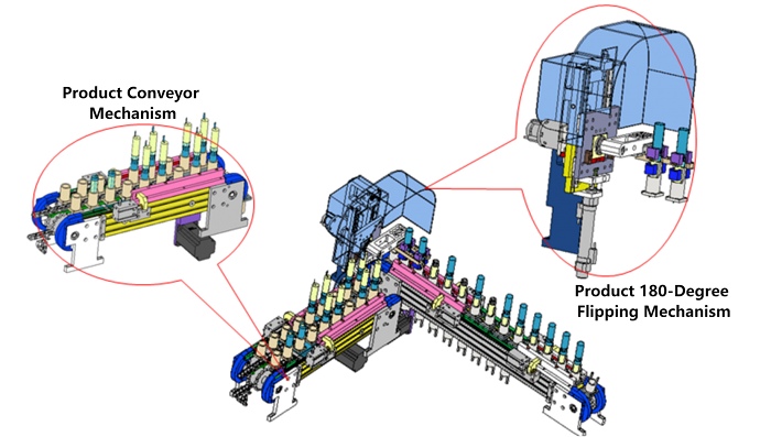
- Steel Can and Cell Assembly Mechanism Model Diagram (2):
The product is clamped by grippers, rotated 180° by a rotary cylinder, and placed onto the product chain conveyor mechanism.
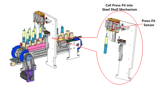
- Cell Pressing into Steel Can Mechanism Model Diagram:
Cell pressing into the steel can is monitored by a pressure sensor to determine whether the cell is correctly inserted or defective.
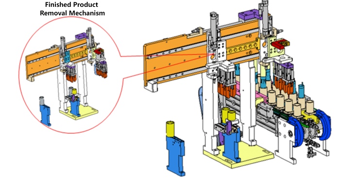
- Finished Product Transfer Out Mechanism Model Diagram:
The finished product is clamped by grippers and moved out by a cylinder.
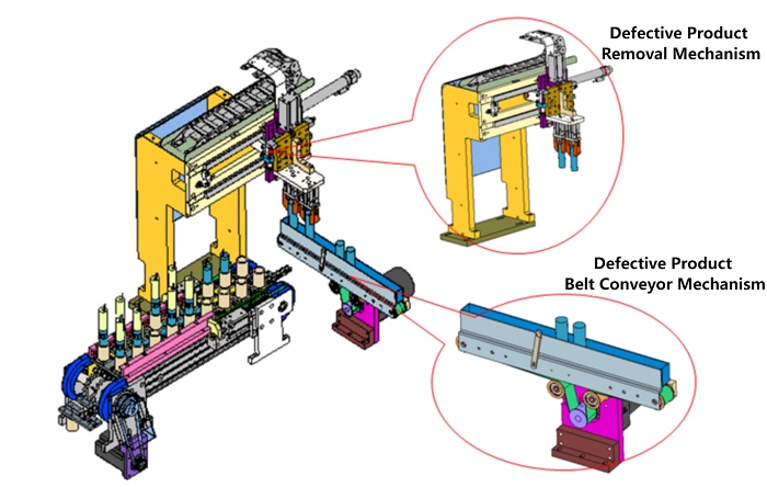
- Defective Product Transfer Out Mechanism Model Diagram:
Defective products are removed by a gripper and placed onto a belt conveyor.
- Equipment Technical Performance Indicators:
1. Capacity: ≥60 PPM
2. Product Yield: ≥99%
3. OEE: ≥90%
4. Equipment Dimensions: L2500 × W2000 × H1900 mm
5. Operating Temperature: Room temperature
6. Relative Humidity: ≤65%
7. Power Supply: AC 220V / 50Hz, 3 kW
8. Compressed Air: Pressure >0.5 MPa; flow rate 180 L/min
|
No. |
Component |
Origin / Brand |
|
1 |
Pneumatic Components |
SMC, Mindman |
|
2 |
PLC Controller |
Mitsubishi, Omron, Hiconics |
|
3 |
Touch Screen |
Weintek, Kinco |
|
4 |
Intermediate Relay |
Schneider |
|
5 |
Servo Motor |
Panasonic, Delta, Hiconics |
|
6 |
Circuit Breaker |
Schneider |
|
7 |
Fiber Optic Sensor |
KEYENCE |
|
8 |
Pressure Sensor |
ResTest |
|
9 |
CCD Inspection System |
Basler |
|
10 |
Linear Guide |
Misumi, Hiwin |
|
11 |
Stepper System |
Yako, Bolong, SLD |
|
12 |
Other Standard Hardware Parts |
Misumi, IHD |
|
No. |
Item |
Technical Parameters |
Remarks |
|
1 |
Applicable System |
Automatic loading of cylindrical lithium-ion cells, OD measurement, automatic rejection of out-of-spec cells, automatic insulation disk loading, automatic tab bending, and automatic shell insertion. |
|
|
2 |
Product Specification |
Lithium-ion cell: diameter 18 mm (anode with single or double tabs) |
|
|
3 |
Mechanical Assembly Speed |
60 pcs/min |
|
|
4 |
Cell Tab Angle Deviation Range |
±15° (incoming material) |
|
|
5 |
Automatic Cell Distribution |
Feeding via front-end conveyor and servo manipulator |
|
|
6 |
CCD Inspection of Cell Height, Diameter, and Missing Positive Tab |
Uses CCD to check cell height, diameter, and positive tab presence |
Standard block calibration |
|
7 |
Rotary Table Assembly Mechanism |
Cells are assembled at each station via rotary table, diameter approx. 750 mm |
High-precision cam indexer |
|
8 |
Negative Inner Tab Inspection and Alignment |
Position detected by fiber optics, corrected by probe mechanism |
|
|
9 |
Insulation Disk Punching and Assembly |
Disks cut by die and picked for placement on the core |
|
|
10 |
Negative Inner Tab Bending |
Elastic bending block adapts to tab length differences; insulation disk pressed before bending |
|
|
11 |
Negative Outer Tab Alignment |
Outer tab aligned via fiber optic detection |
|
|
12 |
Negative Outer Tab Bending |
Elastic bending block adapts to tab length differences; insulation disk pressed before bending |
|
|
13 |
Steel Can Auto Loading, Dust Removal, and Mouth Inspection |
Includes distribution, dust removal, and mouth inspection |
|
|
14 |
First Shell Insertion |
Guided insertion, lower lifter pushes cell into steel can 1/3 depth, pressure sensor monitoring |
|
|
15 |
Second Shell Insertion |
Pushes cell to 2/3 depth; pressure sensor triggers overload protection & alarm |
Pressure varies with cell OD & can ID |
|
16 |
Insertion Detection & Defective Rejection |
Fiber optics confirm position; rejects and unloads defects |
|
|
17 |
Product Line Output |
Transfers to tray conveyor line |
|
|
Code |
Function Name |
Function Requirements |
Remarks |
|
1 |
Steel Can Loading |
1. Loading Methods |
Steel Can
|
|
Option 1: Transfer incoming steel cans from bags (mouths oriented uniformly, tightly arranged) into conveyor fixtures with mouths down, after suitable mechanical handling. |
|||
|
Option 2 (Recommended): Vibratory bowl feeder → mechanical arm transfers cans to conveyor fixtures. |
|||
|
Option 3 (Recommended): From blister trays → mechanical arm transfers cans to conveyor fixtures. |
|||
|
2. Steel Can Protection – Available. |
|||
|
Must ensure smooth positioning without scratches, plating loss, or deformation. |
|||
|
Noise Requirement: Acceptable to operators. |
|||
|
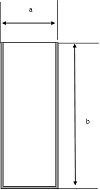
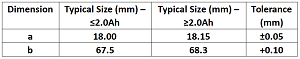
Applicable Steel Can Sizes:
|
|||
|
2 |
Steel Can Roundness Online Inspection |
1. 100% roundness inspection – Not available. |
|
|
2. Automatic rejection of non-round cans – Not available. |
|
||
|
3 |
Steel Can Dust Removal |
1. Must completely and effectively remove dust and metal particles from inner wall – Available. |
|
|
2. Compressed air & vacuum with pressure/vacuum gauge display – Available. |
|
||
|
4 |
Core Loading |
Option 1: Use a robotic arm to automatically locate and pick up the core from a tray, then transfer it to the conveyor fixture of the shell-insertion equipment. —Not using tray-based pick-up; uses conveyor pick-up method instead. |
|
|
The core can have 1 or 2 positive tabs and 1 or 2 negative tabs. —Cannot support two positive tabs; other configurations are acceptable. |
|||
|
5 |
Core Roundness Shaping |
1. Adjust roundness – Available. |
|
|
2. No damage during shaping – Available. |
|
||
|
3. Controllable/displayed pressure – Not available. |
|
||
|
6 |
Core Diameter Pre-check |
1. Adjustable detection range 17.0–17.6 mm – Available. |
|
|
2. Reject defective cores – Available. |
|
||
|
7 |
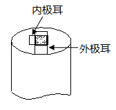
Negative Tab Positioning |
1. Inner/outer negative tab positioning angle deviation ≤3° – Not met. |
|
|
2. Must avoid tab misalignment – Available. |
|||
|
8 |
Insulation Roll Loading |
1. Manual periodic replacement – Available. |
|
|
2. Standby shaft for quick material changeover – Not available (change time short, function not necessary). |
|
||
|
3. Reserved adhesive platform for splicing – Not available (change time short, function not necessary). |
|
||
|
9 |
Insulation Disk Punching & Loading |
1. Punch insulation roll into disks meeting insulation drawing requirements – Available. |
Lower insulation disk
|
|
2. Material requirements – Available: |
|||
|
① Material: PP or PE |
|||
|
② Color: Any |
|||
|
③ Dimensions: per drawing. |
|||
|
3. Cutter material requirement – Available. |
|||
|
4. Easy cutter replacement – Available. |
|||
|
5. Cutter mounting stability – Available. |
|||
|
6. Correct disk placement; missing disk detection with automatic alarm & rejection – Available. |
|||
|
10 |
Negative Tab Bending |
1. After bending must meet: |
Fig. 1 (OK)
|
|
a. Inner/outer negative tabs (angle difference may vary, 0°–360°) must cover center hole, no wrinkles or abnormal bends – Available. |
|||
|
b. No deformation >0.2 mm – Available. |
Fig. 2 (NG)
|
||
|
c. Tab edge to center hole edge deviation ±0.3 mm – Available. |
|||
|
2. CCD detects tab position & defects – Available. |
Fig. 3 (Tab misaligned – NG)
|
||
|
3. Auto rejection of cores missing insulation disk – Available. |
|||
|
4. Defective cores ejected via separate channel – Available. |
|||
|
11 |
Core Insertion into Shell |
1. Adjustable/settable insertion pressure – Available. |
|
|
2. Pressure accuracy 0.01 kgf or equivalent – Available. |
|
||
|
3. No relative position change after insertion – Available. |
|
||
|
4. Tab position meets “Item 8, Function 1” – Available. |
|
||
|
5. No major damage (minor scratches/creases possible). |
|
||
|
6. Positive tab end undamaged (separator may have slight indentations). |
|
||
|
7. Maintain concentricity without offset or squeezing – Available. |
|
||
|
8. Step-by-step insertion in circular station recommended – Servo-driven, no rotation. |
|
||
|
9. Inkjet marking of negative tab position – Not available. |
|
||
|
12 |
Post-insertion Cell Position Adjustment |
1. Automatically orient positive tab upward – Available. |
|
|
2. No cell damage – Available. |
|
||
|
3. No relative movement between components – Available. |
|
l 6.1 Appearance – The load-bearing base frame adopts a square tube welded structure. The upper sealed frame is made of aluminum alloy profiles and enclosed with organic glass. Color: sky blue standard or as specified by the customer.
l 6.2 Operation Interface – Each machine is equipped with an independent touch screen for operation, with a simple interface and easy maintenance.
l 6.3 Layout and Installation Direction – Layout drawings for equipment positioning and installation direction will be provided.
No.
Parameter
Specification
1
Product Yield
99% (refers only to defects caused by the equipment)
2
Equipment Capacity / Speed
≥60 PPM
3
Equipment Availability
≥90% (refers only to downtime caused by the equipment)
4
Electrical Specification
Voltage AC220 ±10%, Power 10 kW
5
Compressed Air
≥0.5 MPa
6
Vacuum
≥ -70 kPa
7
Ergonomics
Machine design must ensure excellent human-machine ergonomics
8
Materials
Preferably aluminum, stainless steel, or electroplated corrosion-resistant materials
VIII. Spare Parts List (Included with Equipment)
|
No. |
Part Name |
Unit |
Qty |
Remarks |
|
1 |
Insulation Disk Punching Die |
Set |
1 |
|
|
2 |
2-Position 5-Way Solenoid Valve |
Pc |
1 |
SMC |
|
3 |
Rotary Unloading Manipulator Gripper |
Set |
1 |
|
|
4 |
Fiber Optic Sensor |
Pc |
1 |
KEYENCE |
|
5 |
Other In-house Manufactured Parts (Normal Wear) |
Set |
1 |
Provided free within 1 year |
|
6 |
List of Vulnerable Parts and Machining Drawings |
Set |
1 |
Auxiliary agreement |
|
7 |
Electrical Drawings |
Set |
1 |
|
|
8 |
Magnetic Switch |
Pc |
1 |
SMC / Mindman |

![]()
![]()

![]()
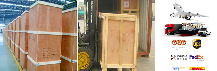
1 Standard exported package: Internal anticollision protection, external export wooden box packaging.
2 Shipping by express, by air, by sea according to customers' requirements to find the most suitable way.
3 Responsible for the damage during the shipping process, will change the damaged part for you for free.
DELIVERY TIME:15-20 days after confirming the order, detail delivery date should be decided according to
production season and order quantity.

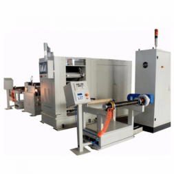
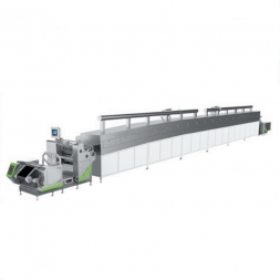
Precision Extrusion Single Side Slot Die Coating Machine For Battery Production
 Subscribe to us
 ONLINE
 +86 13174506016
 Louis@lithmachine.com
 +86 18559646958
 18659217588