- Language:
 English ▼
English ▼
ItemNo :
LITH-LDCK-120MOQ :
1Delivery Time:
5 days
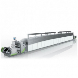
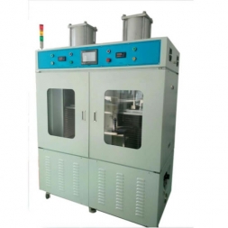
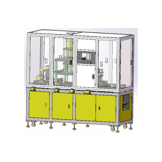
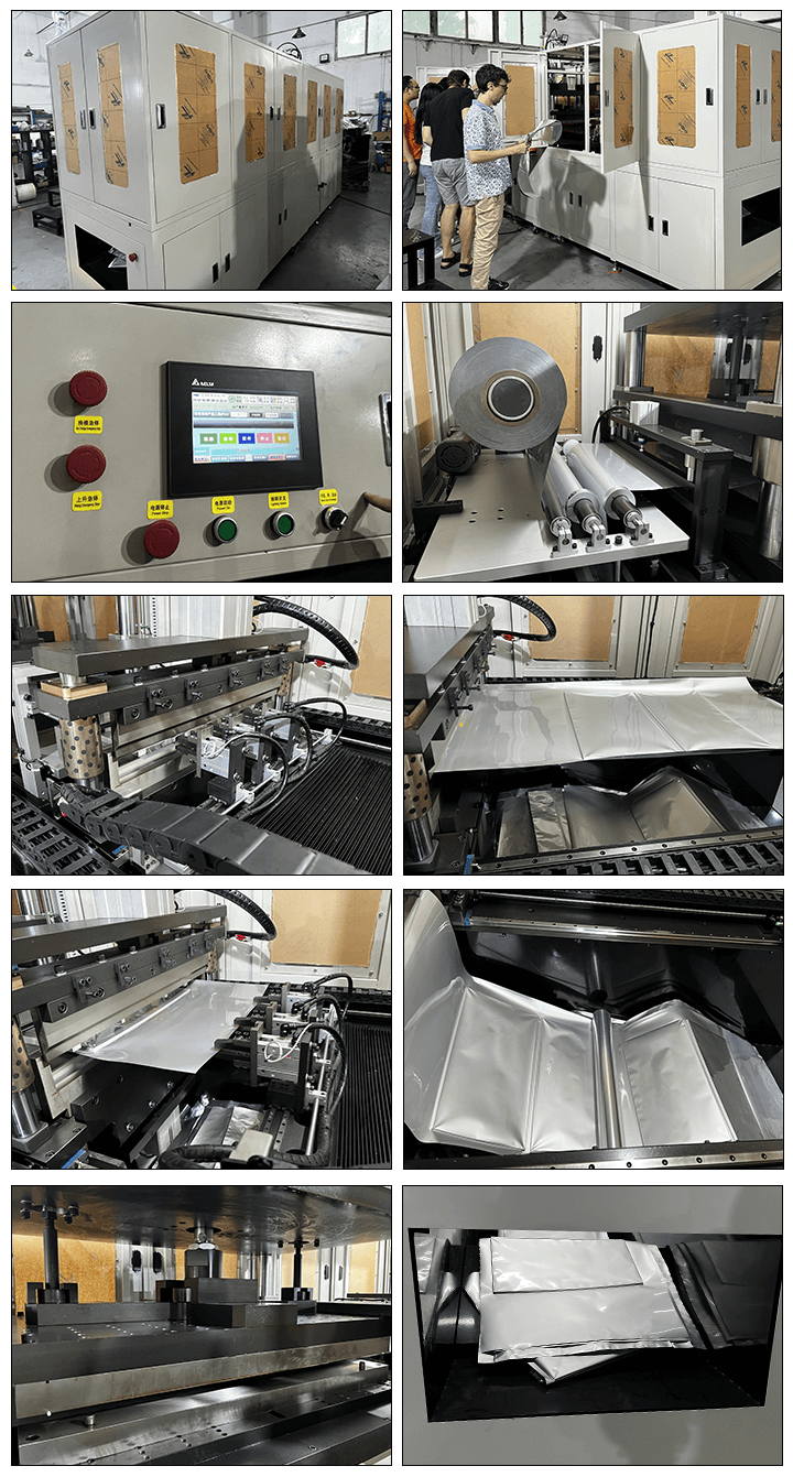
Fully Automatic Pouch Cell Case Forming Machine
– Equipment Function:
1.1.1 Servo motor-driven manipulator for material feeding, with adjustable feeding length up to 240 mm;
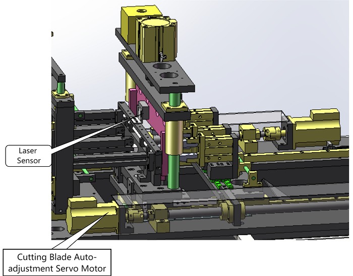
1.1.2 Cutter movement controlled by laser sensor and servo drive, ensuring cutting precision within ±0.15 mm;
1.1.3 All machine actions are controlled by PLC and realized via touchscreen HMI.
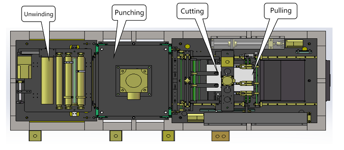
– Operating Principle:
A speed-regulating motor drives the air shaft to unwind the material, with PLC-controlled servo stamping, and servo motor-driven manipulator for material pulling.
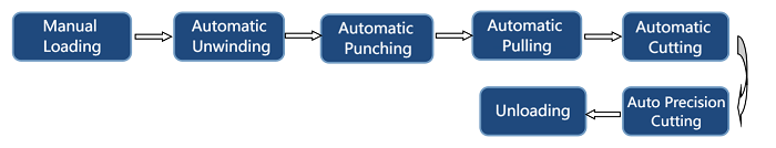
1.2.1 The feeding manipulator clamps the material and transfers it to the target position according to the preset distance;
1.2.2 Upon reaching the target position, the booster cylinder drives the upper mold to close and maintain pressure. The lower servo motor moves upward, pushing the punch to perform deep drawing;
1.2.3 After forming, the punch retracts, and the upper mold lifts under servo control;
1.2.4 The motor-driven transfer system positions the material at a fixed distance;
1.2.5 Once in position, the cutter moves to the cutting location. The cylinder lowers the cutter to perform trimming, ensuring sealing precision;
1.2.6 The transfer mechanism resets and the next cycle begins.
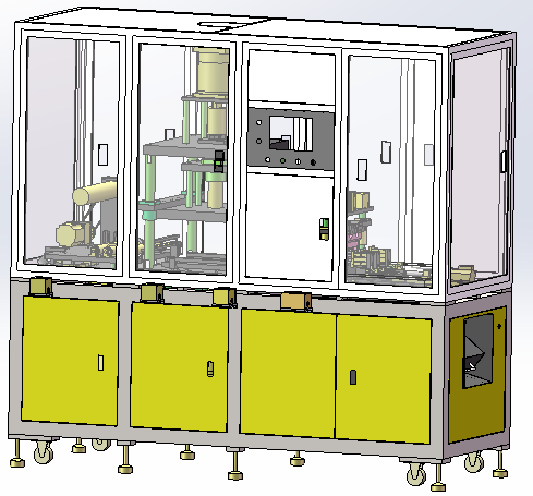
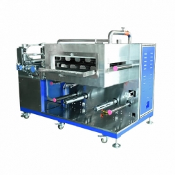
Machine Dimensions: L 202 cm × W 74 cm × H 198 cm (for reference only)
1. Floating roller tension device; material guide rollers made of plastic steel
2. Automatic fiber optic web guiding system integrated with the feeding mechanism
3. Unwinding driven by speed-adjustable motor; cantilever-type air shaft for material roll fixing
1. Power Part: The upper mold adopts a booster cylinder-driven form; the lower mold adopts a servo motor-driven form.
2. During case punching, the motion is driven by a booster cylinder. The control software is compatible with two-step stamping functions. The servo motor on the upper mold ensures at least 40mm of effective stroke and ensures that it meets the power requirements for the maximum product size defined in the technical specifications (over 750W). The servo motor is equipped with the corresponding reducer and coupling. The lifting platform is guided by ball guide posts to ensure stable vertical movement.
The working surface of the material transfer mechanism and the height of the mold mounting base plate: 15-50mm.
3. The stamping part of the equipment (mold position) is equipped with safety light curtains on the front and rear doors, ensuring that there are no blind spots in the safety light curtains to guarantee the safety of operators. A door switch is installed on each front and rear door of the middle section of the equipment to ensure personnel safety.
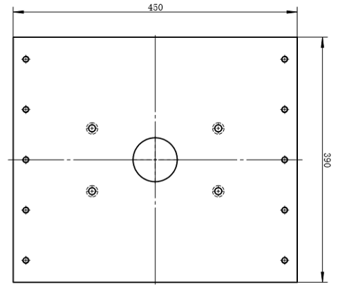
4. The upper mold is connected using an L450mm × W390mm × T40mm 45# steel plate, with four sets of Ø40mm guide posts and linear bearings.
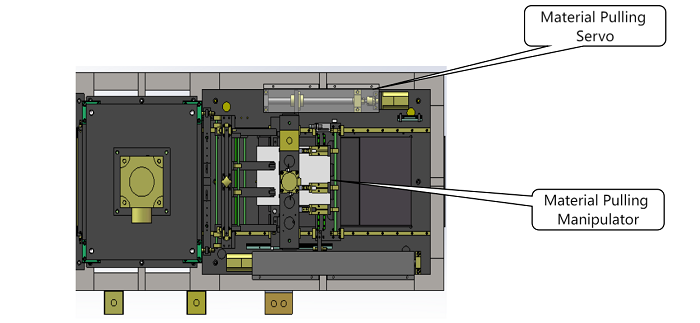
1. Servo motor drives the pulling unit with edge-guided alignment; travel is adjustable, travel range ≥350 mm
2. Material press mechanism installed in front of pulling section
3. Material clamping is achieved by an independent cylinder; clamping blocks are made of anti-slip material
1. Cutter's up-down movement is guided by guide pillars and bushings.
2. Distance between upper and lower cutters after reset: ≥60 mm.
3. The cutting assembly is position-adjustable, guided by a rail; travel range ≥200 mm, effective blade width ≥335 mm.
4. After pulling, the cutter moves right to the fixed-length cutting position to trim the product end, then automatically moves to the high point of the previous foil cavity. Upon detecting the cavity, the cutter moves a fixed length to cut the waste, ensuring sealing position accuracy.
1. Upper frame made of standard aluminum profile, lower frame made of 60×60 mm square steel tubes with 4 mm thickness, welded and painted
2. All protective doors made of sheet metal (excluding feeding side); top doors include viewing windows; each door fitted with safety sensor; sheet metal thickness ≥1.5 mm
3. All exhaust ports of solenoid valves and manifold blocks are fitted with resin mufflers
4. Noise reduction treatment for all air pipes and cable entry/exit points
5. Noise level of all machine sections: ≤80 dB
1. 65536-color true-color touchscreen
2. HMI must be intuitive and user-friendly; buttons sized to prevent accidental double-press
3. Hardware buttons on the panel: Power ON/OFF, Start, Stop (latching), Emergency Stop
4. All stations accessible manually from HMI, each with single-function interface; grouped actions under same screen, no page turning required
5. HMI must display cumulative and shift-based Pocket forming and cutting quantities, with reset function
6. Complete fault alarm and self-diagnosis functions required; names of components in alarm messages must match HMI labels exactly
7. In manual mode, interlocking logic must be in place between interdependent actions of each functional unit
|
Item |
Component |
Brand |
|
1.5.1 |
Pneumatic Components |
AirTAC / YSC |
|
1.5.2 |
Switches / Electrical Components |
Chint |
|
1.5.3 |
Sensors |
Panasonic / Omron / Keyence |
|
1.5.4 |
PLC |
Panasonic |
|
1.5.5 |
Touchscreen |
Delta |
|
1.5.6 |
Ball Screw / Linear Rail |
TBI / Dinghan |
|
1.5.7 |
Motors & Drivers |
Mitsubishi |
|
1.5.8 |
Machine Frame |
Lower: square tube welded + painted; Upper: aluminum profile + transparent acrylic panels |
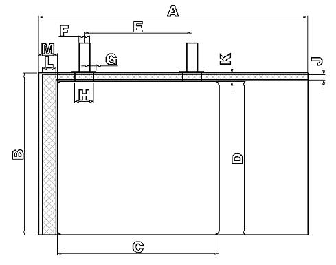
Length: 12 cm (Double-Pit B)
Width: 30 cm (including airbag A)
|
Code |
Name |
Parameter |
|
A |
Case width (incl. gas bag) |
60–300 mm |
|
C |
Body width |
30–250 mm |
|
B |
Body length |
30–120 mm |
|
Item |
Description |
Requirement |
|
Equipment Performance |
Efficiency, Quality |
First-pass yield ≥99.5% (excluding defective incoming material) |
|
Product Quality |
Servo system repeat positioning accuracy: ±0.03 mm |
|
|
Cutting Precision |
±0.15 mm |
|
|
Capacity |
PPM: <30 PPM (based on 2 pcs per cycle), <15 PPM (based on 1 pcs per cycle) |
|
|
Machine Failure Rate |
≤5% |
|
|
Product Changeover |
Changeover time ≤1 hour/person (excluding mold tuning time) |
|
|
Material Compatibility |
Ø35 cm × 30 cm |
|
|
Mechanical Section |
Equipment Dimensions |
L 2020 mm × W 725 mm × H 1900 mm |
|
Machine Weight |
Load-bearing ratio: <500 kg/m² |
|
|
Main Component Selection |
Ball screw/linear rail: TBI / Dinghan |
|
|
Cutting mechanism standardized |
||
|
Wearing parts standardized |
||
|
Electrical Section |
Power Input |
4500 W, 3-phase 380V |
|
Main Component Selection |
Pneumatic: AirTAC / YSC |
|
|
Sensors: Panasonic / Omron / Keyence |
||
|
PLC: Panasonic |
||
|
Motors & Drives: Mitsubishi |
||
|
Switches & Electrical: Chint |
||
|
Touchscreen: Delta |
||
|
Electrical Wiring |
All wiring, gas pipes, and tubing must be clearly labeled |
|
|
PLC must reserve at least 5 I/O terminals and communication ports (Ethernet, RS232, etc.) |
||
|
Software |
Provide PLC source code for equipment operation control and HMI touchscreen program source code (with annotations) |
|
|
Provide all required software installations, including drivers, industrial control card software, etc. |
4.1 Electrical:
– Power: 4500 W, 3-phase AC 380V
4.2 Compressed Air:
– ≥0.5 MPa, 20 L/min
4.3 Weight:
– Total: Approx. 800–1500 kg
– Load-bearing ratio: ≤500 kg/m²
4.4 Environment:
– Room temperature: 10–40°C
– Humidity: 30–70% (no condensation)
– No flammable or corrosive gases
4.5 Machine Frame:
– Reinforced structure, suitable for forklift transport
4.6 Installation Location:
– Standard workshop

![]()
![]()

![]()
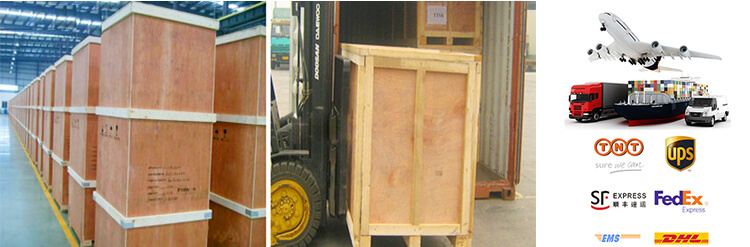
PACKAGE:
1 Standard exported package: Internal anticollision protection, external export wooden box packaging.
2 Shipping by express, by air, by sea according to customers' requirements to find the most suitable way.
3 Responsible for the damage during the shipping process, will change the damaged part for you for free.
DELIVERY TIME:15-20 days after confirming the order, detail delivery date should be decided according to
production season and order quantity.

 Subscribe to us
 ONLINE
 +86 13174506016
 Louis@lithmachine.com
 +86 18559646958
 18659217588