- Language:
 English ▼
English ▼
ItemNo :
LITH-XFT450MOQ :
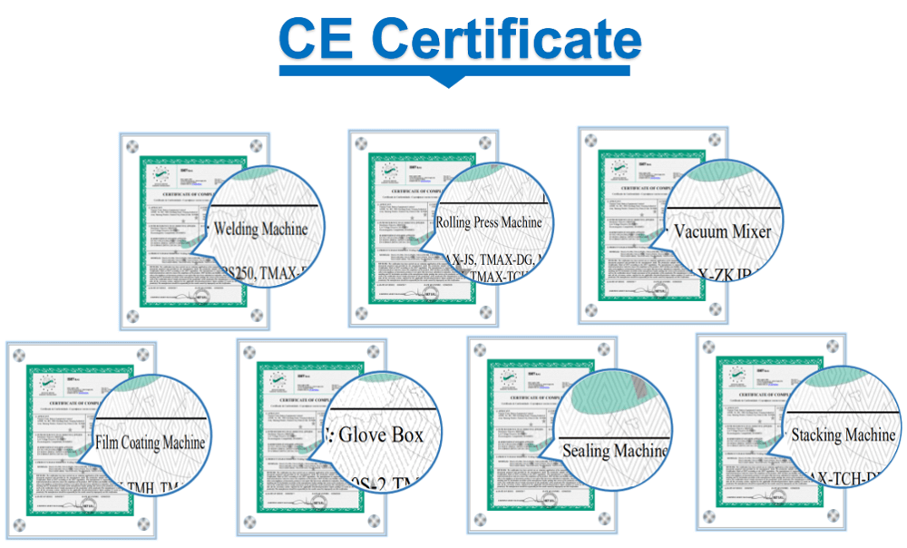
1Compliance:
CE CertifiedWarranty:
2 yearsDelivery Time:
5 days
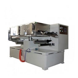
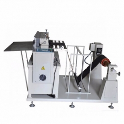
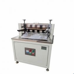
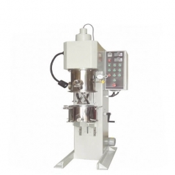
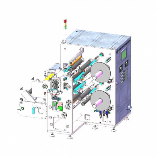
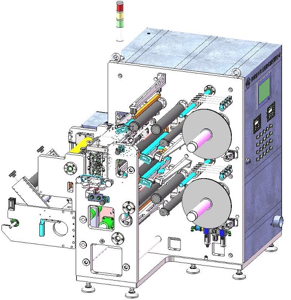
High-Efficiency Roll-to-Roll Electrode Cutting Machine for Lithium Battery Production
The Slitting Machine is primarily used for slitting lithium-ion battery electrode sheets. It is a mature and stable model widely used by our company. The machine supports a slitting width range of 15–380 mm, is user-friendly, and meets various slitting process requirements. It adopts a dual-shaft rewinding structure: the electrode sheet is mounted on the unwind shaft, passively unwound via the drive roller, and guided automatically. After passing through the slitting blades and iron powder removal unit, the electrode sheet is slit and rewound according to process requirements. The machine is easy to operate, with simple loading and threading, stable performance, and excellent slitting results.
· Production Capacity: Max mechanical speed is 80 m/min; typical production speed is 0.5–50 m/min with stepless adjustment.
· Rewinding Alignment Accuracy: ≤ ±0.5 mm (assuming good incoming material quality).
· Pass Rate: ≥ 99% (excluding factors such as poor incoming material).
· Utilization Rate: ≥ 95% (excluding material replacement and incoming quality issues).
|
No. |
Component Name |
Description |
Quantity (sets) |
|
1 |
Main Frame Assembly |
Electrical cabinet, side plates, mounting panels |
1 |
|
2 |
Unwinding Unit |
Air-expanding shaft, tension roller, locking cylinder, web guiding unit |
1 |
|
3 |
Splicing Platform |
Pressure cylinder, pressure bar, splicing platform |
1 |
|
4 |
Unwind Tension Unit |
Tension controller, sensors, rollers |
1 |
|
5 |
Drive Unit |
Motor, drive roller, press roller, pressure adjustment system |
1 |
|
6 |
Adjustment Roller Unit |
Pre-slitting and post-slitting upper/lower adjustment rollers |
3 |
|
7 |
Knife Holder Assembly |
Upper and lower knife shafts, adjustment rollers, drive, dust removal |
1 |
|
8 |
Dust Removal Unit |
Blade dust removal and electrode powder brushing with 8 brush boxes |
2 |
|
9 |
Iron Removal Unit |
Magnetic bars and holders, magnetic strength 6000 Gauss |
4 |
|
10 |
Pressing Belt Unit |
Upper and lower pressing belt structures |
1 |
|
11 |
Rewind Tension Unit |
Upper/lower tension systems and sensors |
1 |
|
12 |
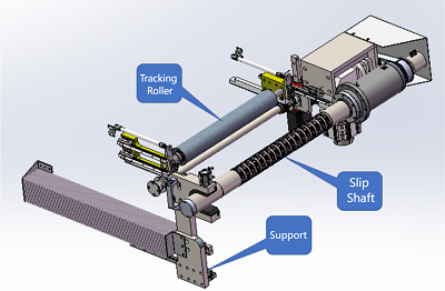
Tracking Roller Unit |
Upper and lower tracking rollers |
1 |
|
13 |
Rewind Unit |
Slip shafts, pressure rollers, motors |
2 |
|
14 |
Edge Trim Unit |
Guide rollers, pressure rollers, waste bins |
1 |
The equipment workflow is outlined as follows:
Web Threading Procedure:
1. Use a transfer cart to load material onto the unwind shaft.
2. Manually thread the electrode sheet through the splicing unit.
3. Guide it through the tension system.
4. Manually feed the sheet to the slitting blades for pre-slitting.
5. Pass the pre-slit sheet through the dust and iron removal system.
6. Place the core sleeve onto the slip shaft.
7. Tape the electrode sheet onto the core sleeve on the slip shaft.
8. Set the required sheet tension.
9. Switch the web guiding system to automatic mode.
10. Press the system start button.
11. The equipment automatically slits and rewinds the material into rolls.
1.5 Main Component Structure
|
Unwinding Part |
3-inch air shaft unwinding |
|
Unwinding Diameter |
Max Φ450 |
|
Web Guiding Control Mode |
Manual/Automatic switch |
|
Web Guiding System |
Photoelectric web guiding system; total guiding stroke 0–80 mm |
|
Tension System |
Tension Range: 50–100 N |
|
Tension Control Accuracy: ≤ ±1.5 N |
|
|
Tension Control Mode: Closed-loop control |
|
Slitting Knife Rack |
Single-side fixed knife rack; upper/lower blade gap adjusted by spacers; engagement depth adjusted via threaded dial |
|
|
Line speed ratio adjustable according to slitting needs |
|
|
Cutting width fixed by precision spacers (tolerance ±0.002 mm) |
|
|
Entry/exit rollers installed; upper/lower blades driven by independent servo motors |
|
Knife Rack Quantity |
One in use, one spare; one rack fully loaded with cutting blades and spacers, one empty rack |
1.5.3 Rewinding Mechanism
|
Electrode Mechanism |
Two sets of 3-inch differential shafts |
|
Rewinding Diameter |
Max Φ350 mm |
|
Edge Waste Collection Device |
Two independent pinch roller systems; proportional line speed collection to prevent material blockage |
|
Tracking Rollers |
Upper/lower rewinding shafts with tracking rollers; seamless tracking ensures winding quality |
|
Rewinding Press Rollers |
One set each for upper/lower shafts; improves rewinding stability and prevents telescoping defects |
|
Rewinding Tension System |
Tension Range: 50–100 N |
|
Tension Control Accuracy: ±1.5 N |
|
|
Tension Control Mode: Closed-loop |
|
|
Structure: Tracking rollers + differential shafts, air pressure controlled by proportional valve |
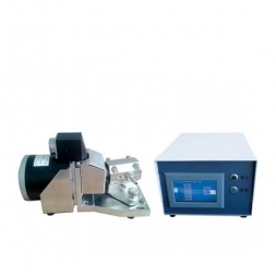
1.5.5 Key Electrical Components
|
Name |
Brand |
Origin |
|
PLC |
Panasonic |
Japan |
|
Touchscreen |
WEINVIEW |
Taiwan, China |
|
Tension Control System |
AIBO |
Shenzhen, China |
|
Magnetic Powder Brake |
KEJIA |
Shenzhen, China |
|
Tension Sensor |
AIBO |
Shenzhen, China |
|
Inverter |
MITSUBISHI |
Japan |
|
Servo Motor |
Panasonic |
Japan |
|
Pneumatic Solenoid Valve |
AIRTAC |
Taiwan, China |
|
Cylinder |
AIRTAC |
Taiwan, China |
|
Rotary Encoder |
OMRON |
Japan |
|
Circuit Breaker |
CHINT/NXB-63 3P |
Imported |
|
Linear Guide |
HIWIN |
Taiwan, China |
|
Bearing |
NSK/Imported |
Japan |
|
Differential Shaft |
|
TMAX Custom |
|
Dust Extraction System |
|
TMAX Custom |
|
Knife Rack Cart |
XHL-1000 |
TMAX Custom |
|
Knife Rack |
|
TMAX Custom |
3.1 All slitting blades diameter φ100, tungsten carbide:
· Negative electrode top blade life ≥ 500,000 m, regrindable ≥ 10 times
· Positive electrode top blade life ≥ 300,000 m, regrindable ≥ 10 times; each regrind yields ≥ 200,000 m
· Bottom blade single side life ≥ 500,000 m; reversible; combo spacer option available per customer
1.
2. Max speed 80 m/min; typical production 0–50 m/min stepless
3. Equipment weight ≥ 2.5 t ensures stability during high speed operation
4. Fixed spacer knife rack: spacer face parallelism ≤ 0.005 mm; simple structure; easy for novice or experienced operators
5. Servo driven cutter and rewind ensure stable, reliable performance
6. Servo driven differential shaft rewind simplifies unloading; stable and easy operation
7. Adjustable upper/lower blade speed ratios via touchscreen for optimal slitting
8. High slitting precision: burr ≤ 5 μm longitudinal, ≤ 7 μm transverse (materials must meet specs)
1. Appearance: control cabinet standard; main frame color “Computer White CH131”; other parts chrome plated (provide color swatch if needed)
2. Complies with national safety standards and customer safety codes
3. Includes Chinese operation manual and maintenance handbook
4. Comes with tool kit (hex wrenches, screwdrivers, etc.)
5. Acceptance slit specs: 7 lanes × 58 mm or 59 mm (18650 cell); machine equipped for one spec only for acceptance test
6. Wear parts list:
|
Part Type |
Part Name |
Model |
|
Wear part |
Upper blade |
Φ130×90×1×26° |
|
|
Lower blade |
Φ130×75×3×90° |
7. Delivery kit for one machine (additional items to be purchased separately):
|
# |
Item |
Model/spec |
Unit |
Standard Qty |
Order Qty |
|
1 |
Upper blade |
130×88×1×26° |
pcs |
|
|
|
2 |
Lower blade |
130×70×3×90° |
pcs |
|
|
|
3 |
Tension spring |
H 2.5 mm |
pcs |
|
|
|
4 |
Spacer (upper) |
H 9 mm |
pcs |
|
|
|
5 |
Spacer (upper) |
H 10 mm |
pcs |
|
|
|
6 |
Spacer (upper) |
H 56 mm |
pcs |
|
|
|
7 |
Spacer (upper) |
H 64.5 mm |
pcs |
|
|
|
8 |
Spacer (lower) |
H 18 mm |
pcs |
|
|
|
9 |
Spacer (lower) |
H 12.5 mm |
pcs |
|
|
|
10 |
Spacer (lower) |
H 19 mm |
pcs |
|
|
|
11 |
Spacer (lower) |
H 56.5 mm |
pcs |
|
|
|
12 |
Spacer (lower) |
H 48 mm |
pcs |
|
|
|
13 |
Dual step spacer |
H 25 mm |
pcs |
|
|
|
14 |
Dual step spacer |
H 24 mm |
pcs |
|
|
|
15 |
Blade holder seat |
H 15 mm |
pcs |
|
|
|
16 |
Knife rack |
per design |
set |
|
|
|
17 |
Knife rack cart |
standard size |
unit |
|
|
Note: Each machine is delivered with one slag wheel per slit spec, one knife rack loaded with that spec; additional specs require separate purchase.
![]()
![]()

![]()
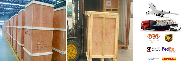
PACKAGE:
1 Standard exported package: Internal anticollision protection, external export wooden box packaging.
2 Shipping by express, by air, by sea according to customers' requirements to find the most suitable way.
3 Responsible for the damage during the shipping process, will change the damage part for you for free.
DELIVERY TIME:15-20 days after confirming order,detail delivery date should be decided according to production season and order quantity

 Subscribe to us
 ONLINE
 +86 13174506016
 Louis@lithmachine.com
 +86 18559646958
 18659217588