Email:Louis@lithmachine.com
ItemNo :
LITH-DS200MOQ :
1Delivery Time:
5 daysEmail :
Louis@lithmachine.com
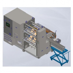
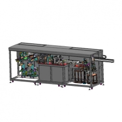
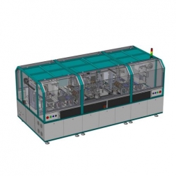
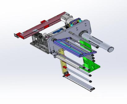
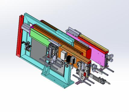
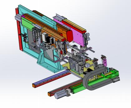
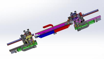
200-Type Automatic Double-Workstation Stacking System for Prismatic Battery Cell Assembly
1. Equipment Introduction
1.1 Equipment Overview
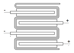
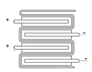
This equipment is mainly used for Z-shaped stacking of prismatic lithium-ion power battery cells.
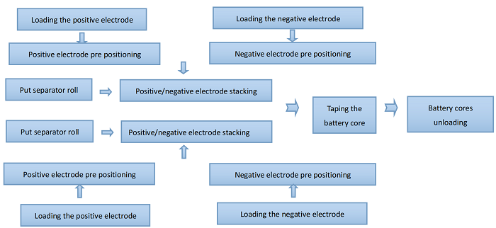
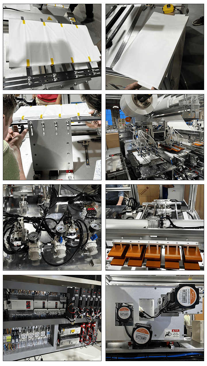
1.2 Working Process
The separator is actively unwound, guided through a tension mechanism, and introduced into the stacking platform. The stacking table drives the separator to move back and forth to place the electrodes. The positive and negative electrodes are stacked first; two sets of mechanical arms with suction cups respectively pick up the positive and negative electrodes from the two material boxes on the left. After precise positioning, they are stacked onto the stacking platform. After stacking is completed, the cell is transferred to the tail tape station via mechanical arm, the separator is cut, and tape is applied automatically. The next cell stacking process starts simultaneously.
Process Flow Diagram:
1.3 Equipment Features
1.3.1 Separator: Active unwinding; alignment correction; alignment accuracy ±0.3mm.
1.3.2 High precision: Through mechanical positioning of the electrodes, stacking accuracy within ±0.3mm is guaranteed.
1.3.3 High efficiency: Overall stacking speed reaches 0.5s–0.8s per piece.
1.3.4 Dust protection: Effective dustproof mechanism installed on material box and pre-positioning station.
1.3.5 Reliability: Positioning pins are installed on high-precision and frequently moving modules.
1.3.6 Multi-sheet & missed sheet protection: Detection and prevention mechanisms avoid multiple or missed sheet stacking.
1.3.7 Tab corner defect detection: Prevents misalignment and defective tab insertion.
1.3.8 Cell stacking discharge (able robotic single cell discharge).
2. Standard Components & Functional Description
|
No. |
Component Name |
Qty/Set |
Description |
|
1 |
Base Frame |
3 |
Supports equipment and provides installation reference |
|
2 |
Auto Feeder Module |
4 |
Custom plug-in feeders; 4 each for anode/cathode; adjustable range; auto stop alarm for material shortage |
|
3 |
Electrode Feed Assist Module |
4 |
Includes brushes, shaker, air blower, vacuum, and anti-multi-sheet design |
|
4 |
Separator Unwinding Module |
2 |
Auto unwinding with constant, adjustable tension and full-axis alignment correction |
|
5 |
Stacking Robot Module |
4 |
Servo-driven; ensures accurate electrode pickup and placement; features dust suction, ultrasonic thickness detection |
|
6 |
Stacking Table Module |
2 |
Servo-driven movement and lifting via precision ball screw |
|
7 |
Cell Transfer Module |
1 |
Robotic arm transfers cells to tape station |
|
8 |
Separator Cutting Module |
2 |
Hot cutting mechanism, cuts after tail length defined |
|
9 |
Tape Application Module |
1 |
Side-taping on all edges (including middle tab); position and quantity adjustable |
|
10 |
Auto Discharge Module |
1 |
Cells are stacked for batch removal, reducing manual labor |
|
11 |
Electrical Operation System |
1 |
Touchscreen interface with emergency stop and power switch |
|
12 |
Control System |
1 |
PLC-based; integrates electrical/pneumatic for space-saving and easy maintenance |
|
13 |
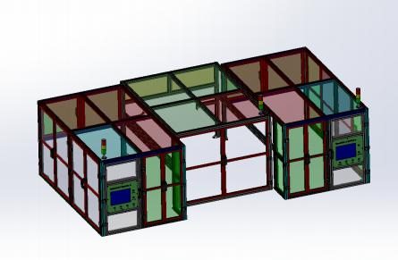
Dustproof Cover |
1 |
Aluminum frame with acrylic cover, includes interlock switch |
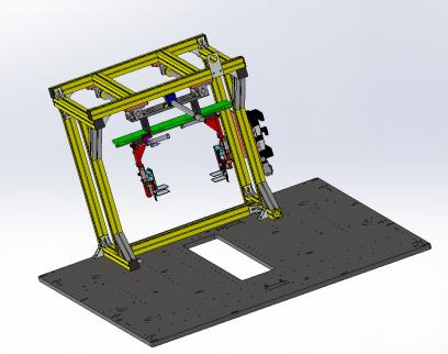
2.1 Base Frame
Function: Provides a flat, stable reference plane for moving parts.
Structure: High-strength square steel tubes welded and surface treated with baking finish. Carbon steel baseplate is machined flat and chrome-plated.
2.2 Auto Feeder Module
Function: Plug-in custom feeders (4 each for positive/negative). Adjustable for size. Ensures reliable electrode pickup. Auto stop with material shortage detection.
2.3 Electrode Feed Assist Module
Function: Includes brush, shaker, air blowing, vacuum cleaning, and anti-multi-sheet mechanisms.
2.4 Separator Unwinding Module
Function: Automatically unwinds separator with constant tension and alignment correction.
2.5 Stacking Robot Module
Function: Servo-driven accurate pickup and placement, includes dust suction, ultrasonic thickness detection to prevent multi-sheet stacking.
2.6 Stacking Table Module
Function: Servo-driven linear and vertical movement; powered by precision ball screw.
2.7 Cell Transfer Module
Function: Robotic arm automatically transfers cell to taping station.
2.8 Separator Cutting Module
Function: Hot blade cuts separator after tail length defined.
2.9 Tape Application Module
Function: Applies tape on four sides (including tab area); tape position and quantity configurable.
2.10 Auto Discharge Module
Function: Cells are stacked and discharged in batches, reducing operator workload.
2.11 Electrical Operation System
Function: Operated via touchscreen, includes emergency stop and power switch.
2.12 Control System
Function: PLC-based with servo/stepper for fast response and short scan cycles. MES system compatible for production data tracking.
2.13 Dustproof Cover
Function: One acrylic cover with interlock switch.
3. Process Specifications
3.1 Material Specifications
|
Material |
Feed Type |
Length (mm) |
Width (mm) |
Thickness (µm) |
Inner Dia |
Max Outer Dia |
|
Cathode |
Sheet |
40–100 |
90–320 |
80–320 |
– |
– |
|
Anode |
Sheet |
40–100 |
90–320 |
80–320 |
– |
– |
|
Positive Tab |
– |
2–40 |
90–320 |
12–30 |
– |
– |
|
Negative Tab |
– |
2–40 |
90–320 |
8–20 |
– |
– |
|
Separator |
Roll |
– |
90–320 |
10–40 |
φ76.2 |
φ300 |
|
Tape |
Roll |
20–40 |
10–30 |
100–200 |
φ76.2 |
φ150 |
Notes:
1. Electrode length refers to size along tab direction (excluding tab length).
2. No significant powder loss or edge waves. Burrs <15µm. Die-cutting tolerance <0.2mm.
3. No curling or sticking between electrodes.
4. Separator snake error: ±1.0mm per 1000mm.
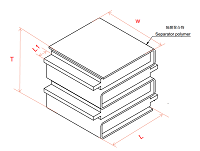
3.2 Cell Specifications
|
Item |
Spec (mm) |
Cell diagram |
||
|
Cell Length (L) |
40–100 |
|
||
|
Cell Width (W) |
90–320 |
|||
|
Cell Thickness (T) |
5–40 |
|||
|
Tab Exposure (L1) |
2–40 |
|||
|
Tab Orientation |
Opposite sides |
|||
|
Total L + L1 |
≤140 |
|||
|
|
|
|||
4. Technical Parameters
|
Item |
Technical Parameter |
|
Single sheet stacking time |
1.1–1.5s (varies by electrode size) |
|
Auxiliary time per cell |
≤15s |
|
Electrode-to-separator alignment |
±0.3mm |
|
Separator edge alignment |
±0.4mm (no tail) |
|
Adjacent electrode alignment |
±0.3mm |
|
Overall stacking accuracy |
±0.5mm |
|
Number of layers |
Adjustable within thickness range |
|
Discharge method |
Cell stack |
|
Fault maintenance |
Alarms cleared within ≤10 min |
|
Uptime (OEE) |
98% (equipment-only faults) |
|
Qualification rate |
99.2% (equipment-only defects) |
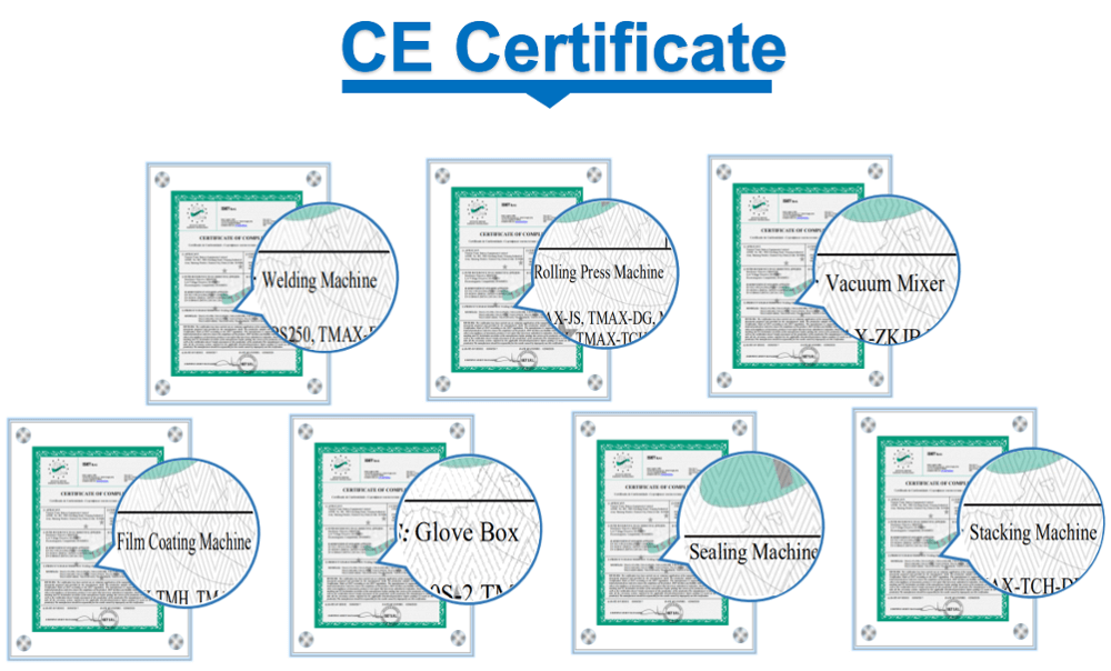
5. Standard Parts Note: Motors and PLCs must have China CE certification.
|
No. |
Name |
Brand |
Note |
|
1 |
Cylinder |
AIRTAC |
|
|
2 |
Magnetic Switch |
AIRTAC |
|
|
3 |
Linear Guide |
HIWIN/DINGHAN |
|
|
4 |
Ball Screw |
TBI |
|
|
5 |
Servo Motor/Drive |
Panasonic/Qinglan/Leadshine/Yankong/Inovance |
|
|
6 |
Solenoid Valve |
AIRTAC/SMC |
|
|
7 |
PLC |
OMRON |
|
|
8 |
Sensor |
Daochuan/OMRON/PANASONIC/Jiazhuan/KEYENCE |
|
|
9 |
Optical Fiber |
KEYENCE/SUNX/OMRON/PANASONIC |
|
|
10 |
Touchscreen |
Kunlun Tongtai/Weilong/Weinview |
|
6. Changeover Kit
|
No. |
Module |
Part |
Unit |
Qty |
Note |
|
1 |
Electrode Box |
Adjustable Plate |
pcs |
8 |
Within a certain range, components such as the material box, pre-alignment mechanism, and suction cups can be adjusted accordingly. |
|
2 |
Pre-alignment |
Adjustment Plate |
pcs |
4 |
|
|
3 |
Robot Arm |
Suction Plate |
pcs |
4 |
|
|
4 |
Stacking Table |
Compression Plate |
pcs |
8 |
|
|
5 |
– |
Cell Support Plate |
pcs |
2 |
|
|
6 |
Discharge |
Discharge Plate |
pcs |
4 |
|
|
7 |
Taping |
– |
set |
1 |
|
|
8 |
Other |
– |
pcs |
– |
7. Wear Parts List
|
No. |
Name |
Spec/Model |
Unit Price (RMB) |
Manufacturer |
Note |
|
1 |
Suction Nozzle |
Custom |
35 |
Machined |
Clean daily |
|
2 |
Press Plate 1 |
Custom |
680 |
Machined |
10-day lead time |
|
3 |
Press Plate 2 |
Custom |
680 |
Machined |
10-day lead time |
|
4 |
Vacuum Filter |
VFD-3-06 |
90 |
CHELIC |
Weekly cleaning |
|
5 |
Vacuum Generator |
VAB-0706 |
80 |
CHELIC |
Weekly cleaning |
|
6 |
Foam |
– |
– |
Accessory |
Stuck to cell surface |
|
7 |
Teflon |
– |
– |
Accessory |
Stuck to electrode surface |
8. Delivery List
|
No. |
Name |
Qty |
Unit |
Note |
|
1 |
Auto Stacking Machine |
1 |
unit |
Acceptance model |
|
2 |
Solenoid Valve |
1 |
pcs |
Spare |
|
3 |
Sensor |
2 |
pcs |
Spare |
|
4 |
Tool Kit |
1 |
set |
Tools |
|
5 |
Technical Specification |
1 |
copy |
Provided post-contract |
|
6 |
Inspection Report |
1 |
copy |
Delivered with equipment |
|
7 |
User Manual |
1 |
copy |
Delivered with equipment |
|
8 |
Spare Parts List |
1 |
set |
Delivered with equipment |
|
9 |
Changeover Kit List |
1 |
set |
Delivered with equipment |
|
10 |
Wear Parts List |
1 |
copy |
With model/drawing numbers |
|
11 |
Wiring Diagram |
1 |
set |
Provided post-acceptance & 90% payment |
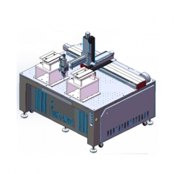
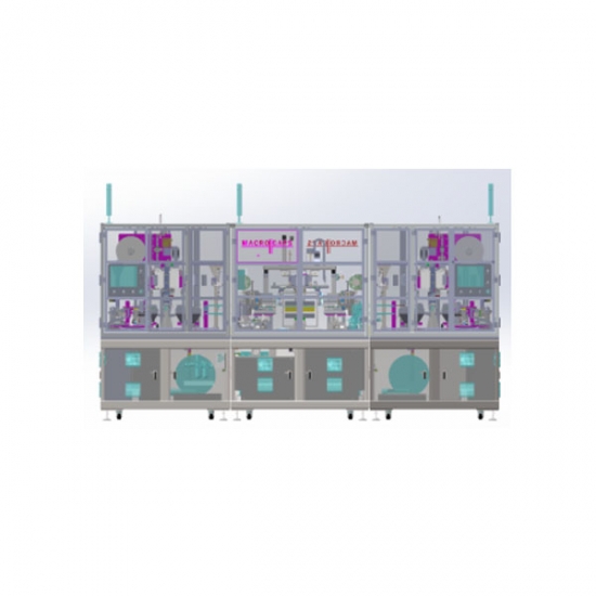
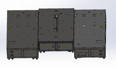
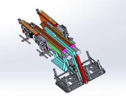
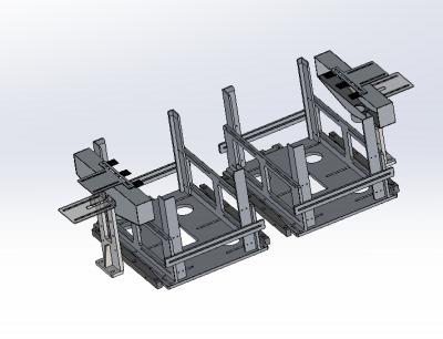
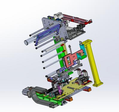
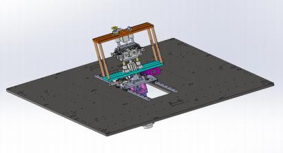
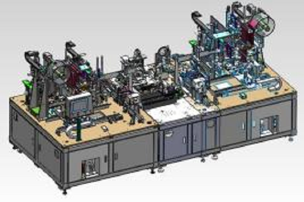
9. Machine Overview & Diagram
|
Item |
Specification |
|
Dimensions |
W4700 × L2300 × H2400mm (final design to confirm) |
|
Weight / Load |
~4000KG; >600Kg/m² |
|
Power |
AC380V ±10%, 3-phase, 20KVA, 50Hz |
|
Air |
0.5–0.7MPa, 200L/min, dry compressed air |
|
Temp/Humidity |
5–35℃; 5–55% RH |
|
Air/Pollution |
No corrosive or conductive dust/gas |
|
Magnetic Field & Vibration |
No interference or strong vibration |
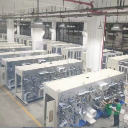
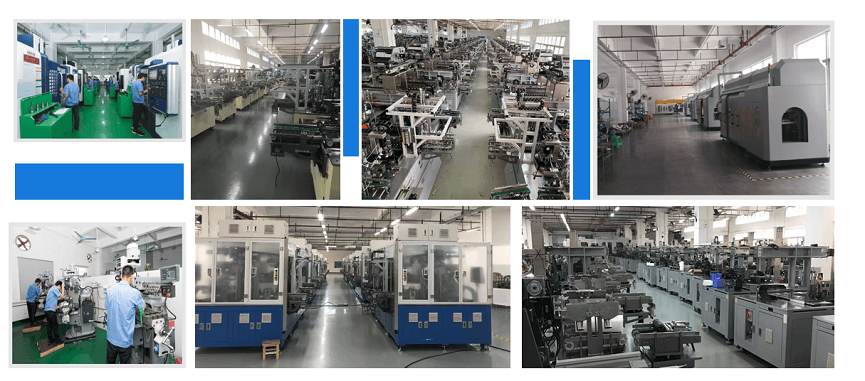
Production Assembly Plant
![]()

![]()
![]()

![]()
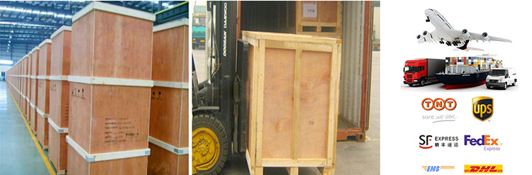
1 Standard exported package: Internal anticollision protection, external export wooden box packaging.
2 Shipping by express, by air, by sea according to customers' requirements to find the most suitable way.
3 Responsible for the damage during the shipping process, will change the damaged part for you for free.
DELIVERY TIME:15-20 days after confirming the order, detail delivery date should be decided according to
production season and order quantity.

 Subscribe to us
 ONLINE
 Louis@lithmachine.com
 +0086 15959378975