ItemNo :
LITH-J200D-BMOQ :
1Compliance:
Warranty:
Delivery Time:
5 days
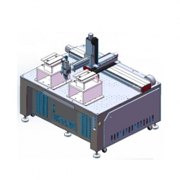
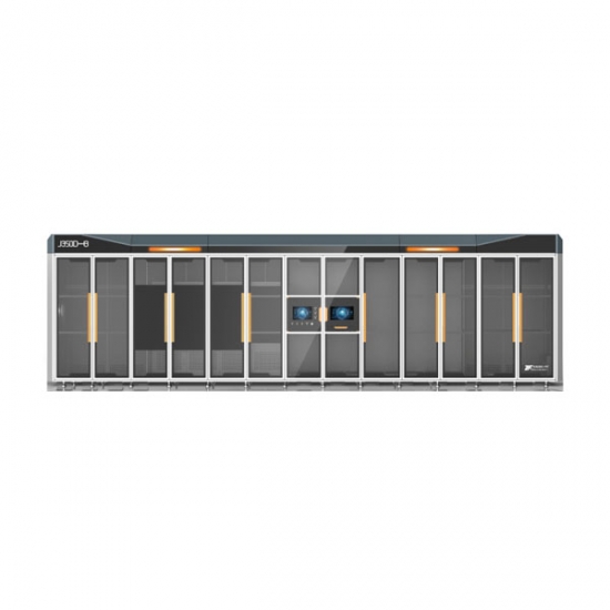
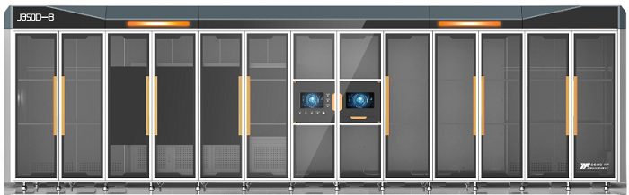
Intelligent Electrode Tab Forming and Die Cutting Line for Lithium-Ion Battery
1. Equipment Overview
1.1 Equipment Function Overview
This equipment is primarily used for cutting cathode and anode sheets (continuous coating process) in the stacking process of power lithium-ion batteries.
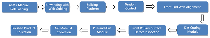
The electrode roll is mounted on the unwinding air shaft of the machine by AGV or manually. The equipment performs automatic unwinding, with an automatic edge alignment system correcting the material during unwinding. Tension is controlled by the tension control system. Before die cutting, a secondary alignment (full web correction) is performed.
After unwinding and buffering, the tab forming station uses a hardware die to punch and form the tabs. A CCD system detects defects on both front and back sides. Then, the material is pulled to the cutting position by the feeding mechanism. After cutting, the sheets are collected in the finished product tray via a conveyor belt. Defective products are automatically rejected into the NG collection box.
1.2 Action Flow
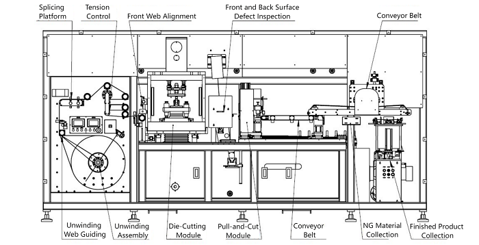
1.3 Equipment Schematic
1.3.1 Equipment Layout Diagram
1.4 Equipment Highlights
l Unwinding Module: Specially designed air shaft to reduce friction with the roll, enabling quick and easy material change. Automatic unwinding driven by servo motor, using roll diameter algorithm to determine roll usage. When the material is nearly exhausted, the system alarms and stops automatically.
l Feeding Mechanism: Uses patented servo feeding system with ±0.2 mm accuracy.
l Cutting Mechanism: Uses patented non-contact cutting structure, low dust and burrs. The cutter position is adjustable via servo motor according to the sheet size to improve width accuracy.
l Integrated Functions: Optional CCD inspection can be integrated to improve equipment utilization.
l High-Speed Precision Metal Die Punching Mechanism: Servo and eccentric wheel mechanism, fast cutting speed, low noise, stable pressure. Quick die change system with forward/backward, left/right, and angle adjustment. Equipped with independent alignment.
l Tape Bypass Function: When adhesive tape is detected, the cutting knife automatically avoids it, preventing cutter and die damage.
l Die Cooling: Built-in cooling system to reduce blade temperature and prolong die life.
l Precision Granite Cutting Platform: Flatness up to 0.01 mm.
l Stacking Neatness: Servo-driven stacking mode, sheet stacking accuracy ±0.5 mm.
l MES Communication: Two network ports reserved. Hierarchical operation control for convenience.
2. Applicable Incoming Materials and Product Specifications
2.1 Specifications of Applicable Incoming Materials
No.
Item
Specification
1
Incoming material width
80–200 mm (including tab)
2
Incoming material thickness
20–250 μm
3
Core diameter of material roll
3 inches
4
Outer diameter / weight of roll
≤550 mm / ≤350 kg
5
Coating type & damage requirements
Continuous coating, single-sided tab, tab damage ≤0.5 mm
6
Tab height
≤25 mm
7
Roll winding alignment
≤±1.5 mm
8
Wave edge height
≤0.5 mm
9
Coating width deviation
≤±0.5 mm
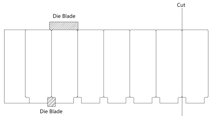
2.2 Electrode Sheet Die-Cutting Method
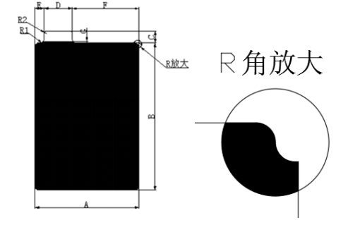
2.3 Customer Product Dimension Confirmation Table
Model
Cathode Size
Anode Size
Tab Size
Tab Pitch
Corner Radius R
Length(B)
Width (A)
Length(B)
Width (A)
3
3
3
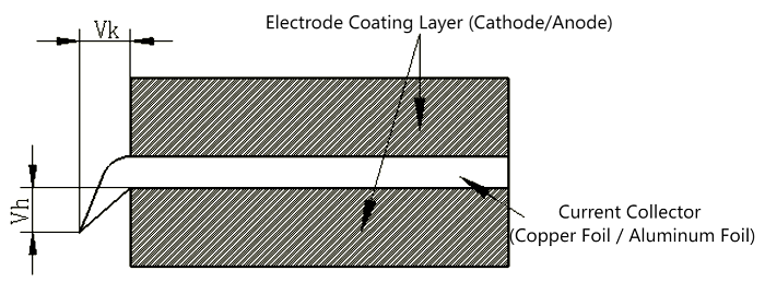
2.4 Electrode Sheet Burrs
l Flat burr (Vk, metal burr): ≤10 μm
l Vertical burr (Vh, metal burr): ≤15 μm
3. Technical Specifications
No.
Item
Specification / Value
Remarks
1
Electrode sheet length
80–200 mm (including tab)
2
Electrode sheet width
80–180 mm
3
Unwinding roll core diameter
3 inches
4
Max outer diameter / weight of roll
≤550 mm / ≤400 kg
5
Production speed
≥25 PPM
6
Electrode dimension accuracy
±0.2 mm
7
Die service life
≥500,000 times after each refurbishment, ≥5,000,000 total
Refurbishable ≥10 times
8
Cutter service life
≥500,000 times after each refurbishment, ≥5,000,000 total
Refurbishable ≥10 times
9
CCD defect detection
Miss rate = 0, False reject rate ≤0.5%
Subject to material quality
10
Finished sheet stacking alignment
±0.5 mm
11
Equipment noise level
≤75 dB (measured at 1 meter from machine)
12
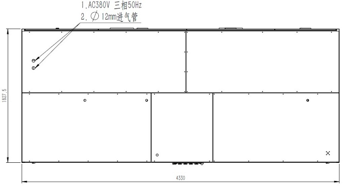
Power supply
AC 380V ±5%, 3-phase, 50Hz
Start power ≤25 kW, operating ≤15 kW
13
Air supply
0.5–0.6 MPa compressed air, consumption: 800 L/min
14
Machine dimensions
Approx. 4400 × 1900 × 2200 mm (main unit)
15
Appearance color
Standard warm gray 1C (color swatch required if customized)
16
Equipment weight
Approx. 5500 kg
17
Floor load capacity
≥750 kg/m²
18
Product yield
≥99.5%
19
Equipment availability rate
≥95%
20
Operating environment temperature
0–50°C
l Unwinding direction: clockwise or counterclockwise selectable
l Fiber optic pen assists with alignment during loading
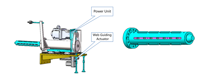
l Equipped with web guiding correction function: accuracy ≤±0.2 mm, stroke ±50 mm
l Equipped with splicing platform and auxiliary marking lines for manual splicing
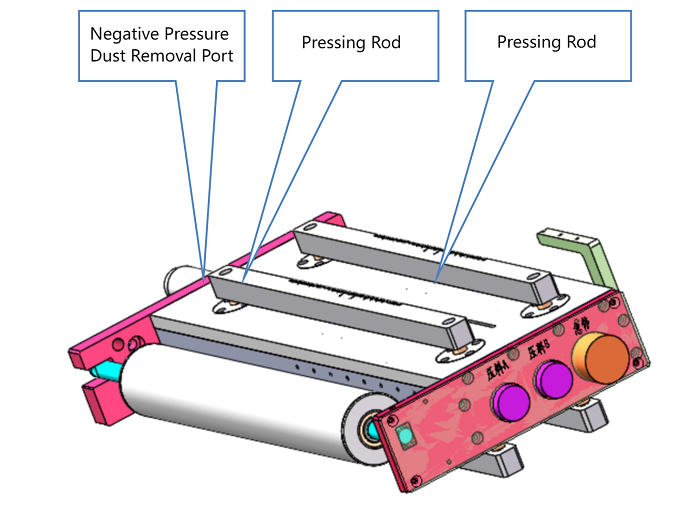
l Non-metal materials used; pressing bar driven by air cylinder with soft contact to avoid damage to electrode sheets
l Dust collection box under blade slot, connected to dust collector via suction pipe
l Embedded scale ruler on splicing platform
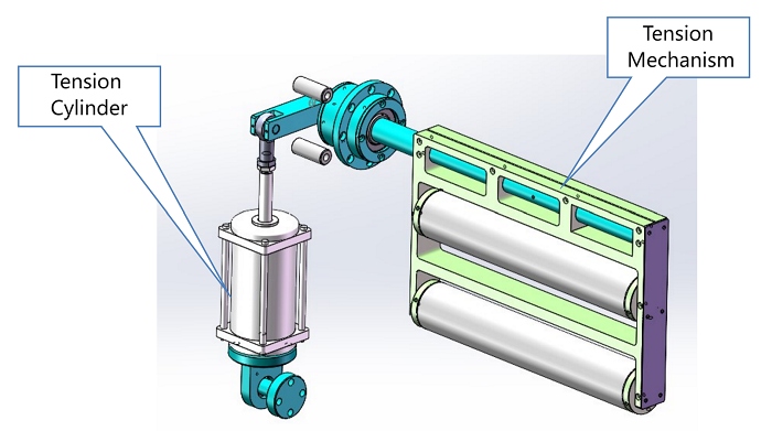
l Swing roller synchronization control; signal detected by potentiometer sent to PLC
l PLC + low-friction air cylinder + electric proportional valve for tension control
l Tension range: 20–100 N, fluctuation during stable operation ≤5%
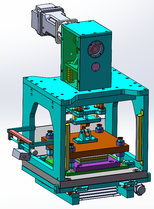
l Electrode tab is formed via a complete precision metal die
l Automatic web guiding correction via CCD to ensure consistent punching position
l Dual color mark sensors detect front-side tape, enabling skip punching
l Safety baffle installed for operator protection
l Die base made of marble for flatness (≤0.01 mm), ensuring stability and preventing deformation
l Quick-change tooling system with alignment pins for easy replacement (<0.5 h)
l Light curtain safety protection required at die position
l Trim scrap collected centrally
l Die punch count monitoring with replacement alerts per preset threshold
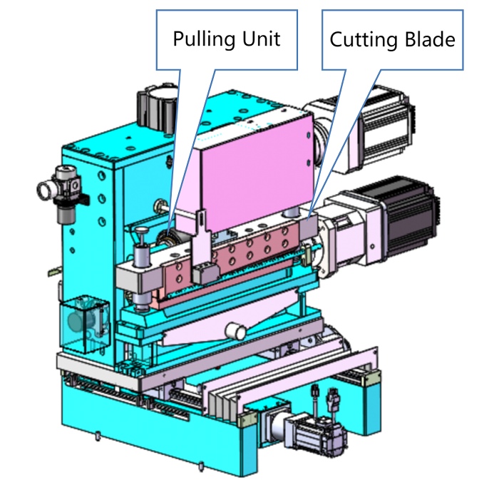
l Patented servo feeding system: max speed 60 m/min, accuracy ±0.2 mm
l EPDM rollers used to avoid dust/particles on surface; ensures flat, mark-free electrode sheets
l Upper rollers rubber-coated, 90° hardness, with brush cleaning
l Lower rollers: HV750 hardened chrome-plated steel, Ra≤0.2 μm
l Upper rollers pressed down by air cylinder to ensure dimensional accuracy
l Cutter drive: servo motor + cam mechanism
l Blade material: imported G5 tungsten steel
l Tool change time ≤0.5 h
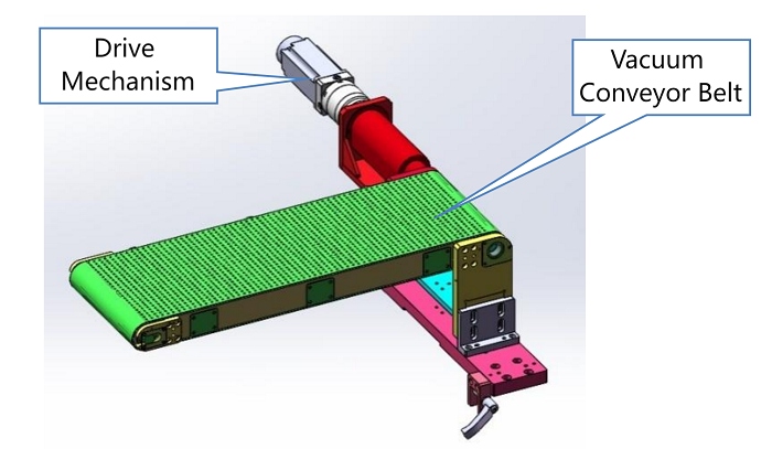
A. Lower Conveyor Belt
l Servo-driven, with electronic cam motion profile for smooth acceleration
l Perforated belt (∅3 mm holes) uses vacuum suction to hold electrode sheets
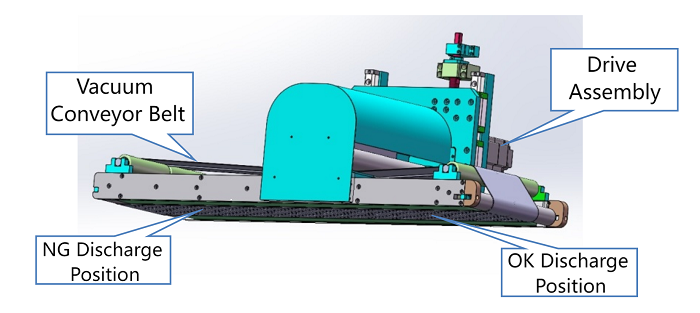
B. Upper Conveyor Belt
l Servo-driven, electronic cam motion for smooth operation
l 1.5 mm thick perforated belt with vacuum suction, segmented into multiple lanes
l Integrated with discharge mechanism
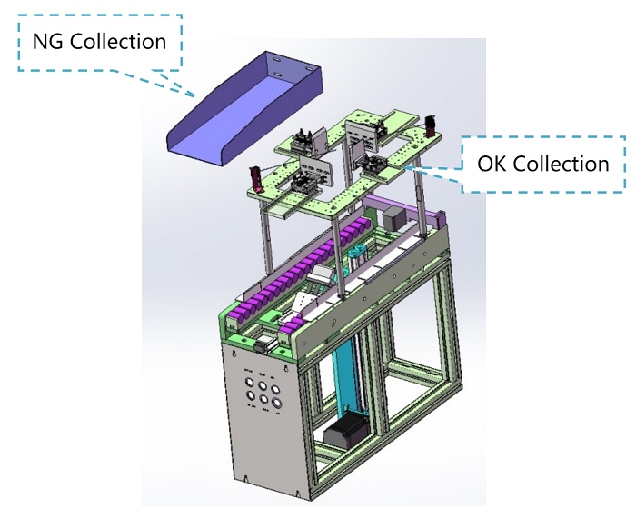
l Sheets are automatically stacked into collection box via belt
l Box equipped with auto-lift and full-load alarm
l Buffer unit installed for temporary sheet holding
l Drop stacking precision: ≤±0.5 mm
l No contact between electrode sheet and box wall during drop
l NG sheets removed automatically; with fail-safe alarms: 3 consecutive NGs → alarm; 5 → machine stop
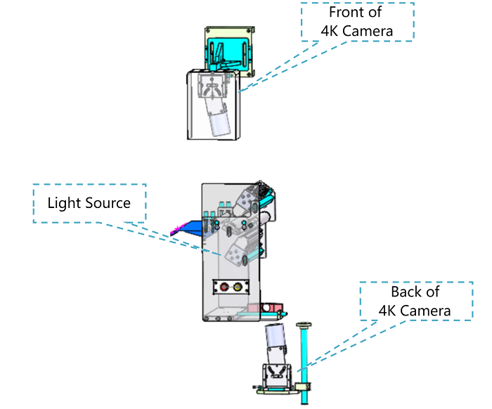
l Linear array cameras scan surface while sheet passes over roller, stitching into full image
l Algorithms analyze image features, output OK/NG signal
l NG rejection device removes defective sheets
l Two 4K line scan grayscale cameras + 300 mm high-brightness linear light source
l Detection width: up to 300 mm
l CCD system exports defect data as CSV file
l AI classifies defects by type
Defect Type
Rejection Threshold
Bright spot
> 0.5 mm²
Foil exposure
> 0.5 mm²
Tape joint
> 20 mm length, >1 mm width
Scratch
>10 mm length, >0.5 mm width
Crack
> 0.5 mm²
Hard particle
> 0.5 mm²
Fish scale (pinhole)
> 0.5 mm²
Powder drop
> 0.5 mm²
Rolling adhesion
> 0.5 mm²
Dried spot, black dot
> 0.5 mm²
Dark spot
> 0.5 mm²
Wrinkle / bent corner
> 2 mm
Edge foil exposure
> 0.5 mm²
Hole
Radius > 1 mm or >20 pixels
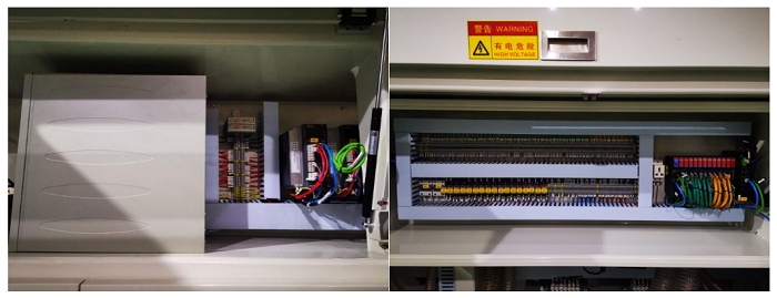
l Composed of one PLC, one 15-inch touchscreen, and other electrical components
l Bus-style wiring reduces cable volume; clean and organized panel
l Separation of high and low voltage wiring to reduce signal interference
l Frame made of high-strength square steel tubes, surface treated by spraying
l Enclosure made of aluminum profile / sheet metal and acrylic for dust protection
No.
Component
Brand
Origin
1
PLC Control System
Trio
UK
2
Web Guiding System
Puliyuan / Bat
China
3
Touchscreen
Weintek
China
4
Servo Motors
Estun
China
5
Tension Controller
Fujikura
Japan
6
Pneumatic Components
SMC / Airtac
Japan / Taiwan
7
Ball Screw & Linear Guides
Hiwin
Taiwan
8
Bearings
NSK
Japan
9
Switchgear & Electrical Parts
Schneider / Panasonic
Germany / Japan
10
Photoelectric Sensors
Omron / Panasonic / Baumer / Julong
Japan / China
11
CCD Camera
Hikvision
China
No.
Name
Specification
Remarks
1
Photoelectric Switch
EE-SX671A
Omron
2
Intermediate Relay
MY2J-12VDC
Schneider
3
Push Button Switch
φ22
Schneider
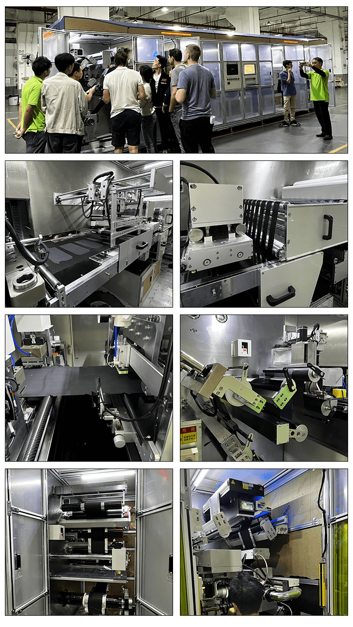
4. Main Components and Functions
4.1 Unwinding Module
4.2 Splice Table (Taping Station)
4.3 Tension Control Module
4.4 Precision High-Speed Punching Module
4.5 Feeding Module (Material Feeding)
4.6 Conveyor Belt System
4.7 Electrode Sheet Collection Unit
4.8 Double-Side Defect Inspection

4.9 Control System
4.10 Machine Frame & Enclosure
5. Main Components List
5.1 Key Components
5.2 Wear Parts List
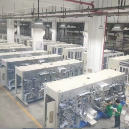
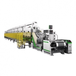
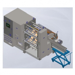
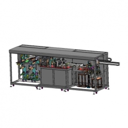
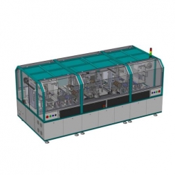
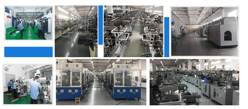
Production Assembly Plant
![]()
![]()
![]()

![]()
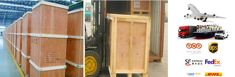
PACKAGE:
1 Standard exported package: Internal anticollision protection, external export wooden box packaging.
2 Shipping by express, by air, by sea according to customers' requirements to find the most suitable way.
3 Responsible for the damage during the shipping process, will change the damaged part for you for free.
DELIVERY TIME:15-20 days after confirming the order, detail delivery date should be decided according to
production season and order quantity.

 Subscribe to us
 ONLINE
 +86 13174506016
 Louis@lithmachine.com
 +86 18659217588
 18659217588