- Language:
 English ▼
English ▼
ItemNo :
LITH-DSMOQ :
1Delivery Time:
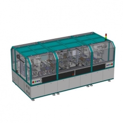
5 daysDouble Workstation Battery Electrode Stacking Machine for Prismatic Cell Manufacturing
1. Equipment Overview
1.1 Function Description
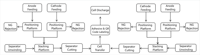
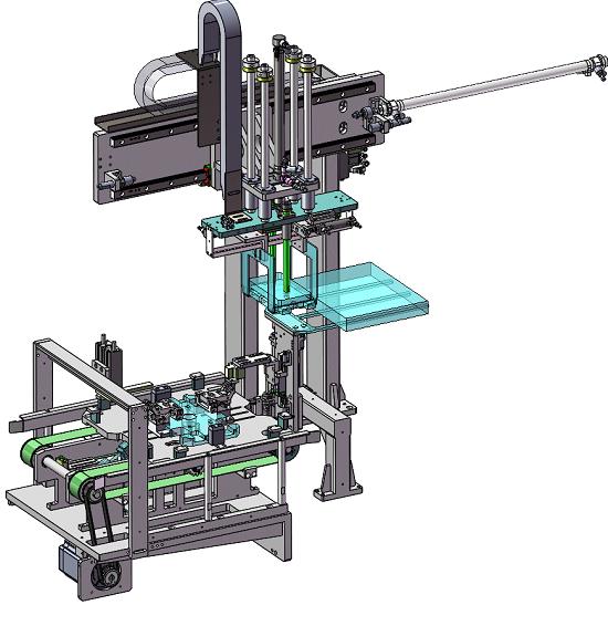
This dual-station stacking machine is mainly used for the "Z"-fold stacking process of prismatic battery cells. It stacks cathode sheets, anode sheets, and separators into a battery cell through the Z-fold stacking process, by side tape application, QR code labeling, and cell unloading into the next process. The equipment consists of the following components: material box feeding mechanism, cathode/anode alignment mechanism, electrode sheet transfer robot, separator unwinding unit, stacking table unit, separator hot-cut mechanism, cell transfer unit, adhesive tape application unit, QR code labeling unit, and cell unloading mechanism. It is used for fully automated production of pouch and prismatic cells.
1.2 Process Flow Diagram
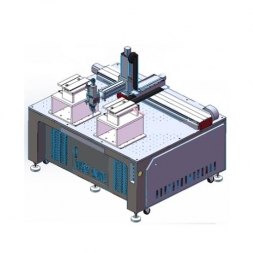
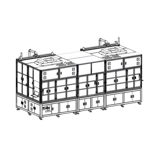
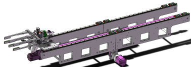
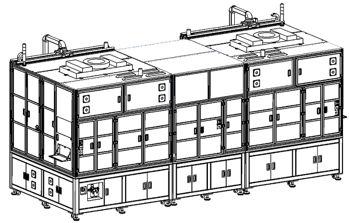
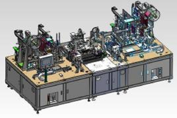
1.3 System Layout
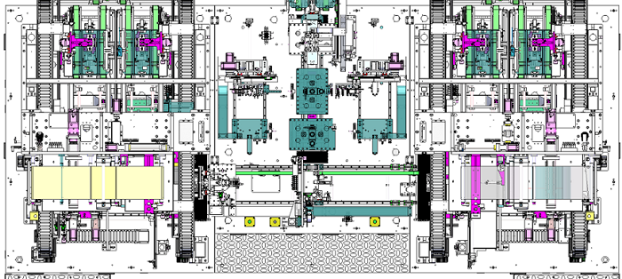
Note: The dimensions in the diagram are for reference only. Please refer to the table below for detailed specifications.
|
Length (mm) |
Width (mm) |
Height (mm) |
Remarks |
|
4800 |
2400 |
2500 |
Reference size |
1.4 Equipment Appearance

2. Product Specifications
2.1 Incoming Material Specifications
|
Material |
Form |
Length (mm) |
Width (mm) |
Thickness (μm) |
Inner Dia. (mm) |
Max Outer Dia. (mm) |
|
Cathode |
Sheet |
60–110 |
110–180 |
100–200 |
— |
— |
|
Anode |
Sheet |
60–110 |
110–180 |
80–180 |
— |
— |
|
Cathode Tab |
— |
10–35 |
10–50 |
7–12 |
— |
— |
|
Anode Tab |
— |
10–35 |
10–50 |
6–10 |
— |
— |
|
Separator |
Roll |
— |
60–110 |
10–30 |
φ76.2 |
φ350 |
|
Tape |
Roll |
— |
10–30 |
15–50 |
φ76.2 |
φ150 |
Remarks:
(1) The length of the electrode is defined as the dimension along the tab direction, with the tab length itself excluded.
(2) Electrode sheets must be free from excessive powder shedding and wavy edges; die-cutting tolerance should be less than 0.3mm.
(3) Electrode sheets should show no significant warping, and there must be no adhesion between individual sheets.
(4) Serpentine deviation of the separator: maximum 1mm per 1000mm length.
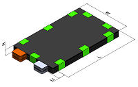
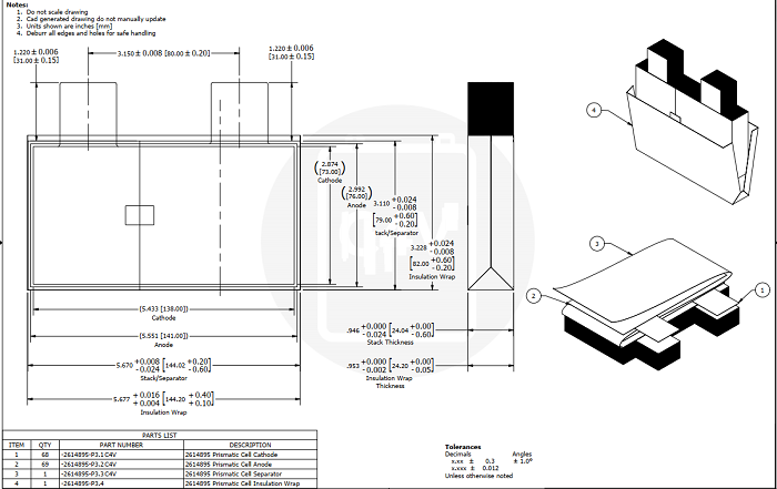
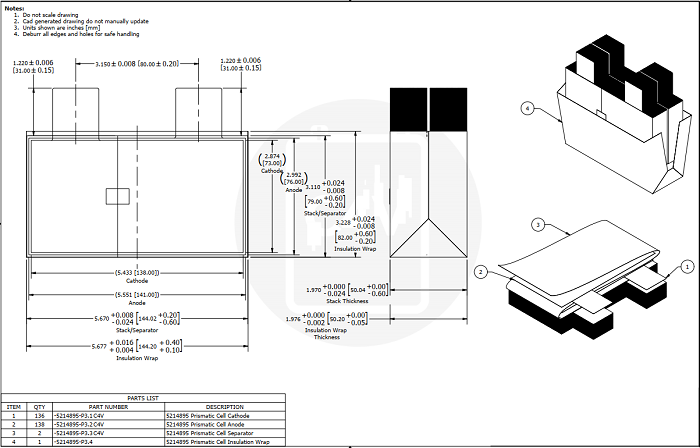
2.2 Product Dimensions
|
Item |
Spec |
Cell |
|
Thickness H (mm) |
10–30 |
|
|
Width W (mm) |
110–180 |
|
|
Length L (mm) |
60–110 |
|
|
Tab Length L1 (mm) |
≤35 |
|
|
Tab Width (mm) |
≤40 |
|
|
Tab Direction |
Same Side |
2.3 Benchmark Cells
Benchmark 1: 30AH cell (20PPM) - 3.9V30AH, 68 cathodes, 69 anodes
Benchmark 2: 60AH cell (10PPM) - 3.9V60AH, 136 cathodes, 138 anodes
3. Equipment Technical Capabilities
|
Item |
Parameter |
|
Production Efficiency |
Whole machine: ≥0.4PPM (Benchmark 1) Single station stacking speed ≤1.8s/pcs Auxiliary time: ≤25s |
|
Yield |
≥99% (machine-caused defects only) |
|
Utilization Rate |
≥98% (machine-related downtime only) |
|
Power Supply |
380VAC±8%, 3-phase 5-wire, 50Hz |
|
Power |
40KW |
|
Compressed Air |
0.5–0.7Mpa |
|
Equipment Weight |
Approx. 5000kg; Floor load ≥600Kg/m² |
|
Cathode-Anode Center Alignment |
≤±0.3mm |
|
Separator-Anode Center Alignment |
Adjacent ≤±0.3mm, Overall ≤±0.5mm |
|
Stacked Cell Alignment Accuracy |
≤±0.5mm |
|
Alignment CPK |
≥1.33 |
4. Configuration List
|
No. |
Module Name |
Qty |
Description |
Configuration |
|
1 |
Feeding Unit |
2 |
1. Magazine positioning accuracy: ±1mm; 2. Positive/negative trays with foolproofing; 3. Anti-double-sheet and dust removal; 4. Connected to logistics line for auto-feeding and empty tray return. |
Standard |
|
2 |
CCD Alignment Platform |
4 |
Positioning accuracy: ±0.1mm; Positioning method: CCD alignment. |
Standard |
|
3 |
Electrode Transfer Robot |
4 |
X-axis positioning accuracy: ±0.02mm. |
Standard |
|
4 |
Separator Unwinding |
2 |
Deviation correction stroke: ±15mm; Correction accuracy: ±0.1mm; Max roll dia.: ≤Φ350mm. |
Standard |
|
5 |
Stacking Table |
2 |
Stack thickness: 10–30mm; Stacking method: Z-fold. |
Standard |
|
6 |
Separator Cutting Unit |
2 |
Cutting method: hot cut; Cutter lifespan: ≥100,000 times; Precision: ±0.3/300mm. |
Standard |
|
7 |
Stacked Cell Clamp |
1 |
Translation accuracy: ±0.05mm. |
Standard |
|
8 |
QR Code Tape Unit |
1 |
Tape width: 10–30mm; Tape roll dia.: ≤150mm;Adhesive position accuracy: ±1mm; Cutter lifespan: ≥200,000 times. |
Optional |
|
9 |
Side Tape Clamp Unit |
1 |
Translation accuracy: ±0.1mm. |
Optional |
|
10 |
Side Tape Unit |
2 |
Tape width: 10–30mm; Tape roll dia.: ≤150mm; Position accuracy: ±0.5mm; Cutter lifespan: ≥200,000 times; Taping method: Finger-C; Tape length: 20–80mm. |
Optional |
|
11 |
Cell Unloading Robot |
1 |
Accuracy of placing cell into tray: ±0.5mm. |
Standard |
|
12 |
Dust Removal System |
1 |
Demagnetization strength: ≥8000Gs; Cleanroom level: ≥Class 100,000. |
Standard |
|
13 |
Operation System |
1 |
Controlled via touchscreen. |
Standard |
|
14 |
Machine Frame Enclosure |
1 |
Welded square tubing frame with paint finish (color per color chart). |
Standard |
|
15 |
Data Management System |
1 |
Reserved for MES interface. |
Optional |
5. Configuration Component Descriptions
5.1 Electrode Sheet Feeding
5.1.1 Function:
The electrode trays are delivered to the machine via logistics line. Upon detection, the robotic arm starts automatically picking sheets from the tray.
5.1.2 Configuration & Parameters:
1. Foolproof tray design: Positive/negative tray base plates have unique cutouts, with sensors to prevent incorrect loading. The machine will alarm if misloaded.
2. Custom adjustable tray bottom plates fit varying electrode sizes. Tray edge includes brush and air-blow systems to prevent double sheets.
3. One tray pickup position per stacking station for both cathode and anode; tray capacity ≥1000 pcs.
4. Positive and negative tray zones are isolated to avoid cross-contamination by dust.
5.2 CCD Alignment Platform
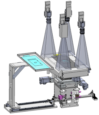
5.2.1 Function:
The electrode picked from the tray is placed onto the alignment platform. CCD inspection and XYZ motion system performs secondary alignment to ensure stacking accuracy.
5.2.2 Configuration & Parameters:
1. CCD vision system with backlight underneath the platform.
2. Vacuum suction plates are used during alignment to prevent edge damage or powder drop.
3. 3-axis correction (X, Y, R) via XYZ modules; accuracy ±0.1mm; stroke: X ±10mm, Y ±10mm, R ±5°.
4. Positive pressure blow and negative pressure suction on both sides maintain surface cleanliness.
5. Ultrasonic dual-sheet detection to identify absence or excess of electrodes. Alarm is triggered for double sheets and operation resumes after removal.
6. NG electrode sheets are auto-rejected. Repeated failures trigger alarm; count threshold is adjustable.
7. All inspection data is stored in the IPC and can be uploaded to MES.
5.3 Electrode Transfer Robot
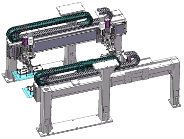
5.3.1 Function:
Driven by linear modules, the inner and outer suction arms move the electrode from tray → alignment platform → stacking table, coordinating with separator unwinding and stacking to complete Z-fold stacking.
5.3.2 Configuration & Parameters:
1. Cathode/anode robots driven by linear modules for high-speed, precise transfer; positioning accuracy ±0.02mm.
2. Z-axis motion by cylinder for inner/outer suction arms, enabling rapid, synchronized movement.
3. Pressure switches monitor vacuum suction; abnormal vacuum triggers alarm and stops the machine.
4. Outer suction arms equipped with high-frequency shake to prevent multi-sheet pick-up.
5. Inner suction arms use silicone nozzles and anti-static foam for secure and non-damaging pick-up.
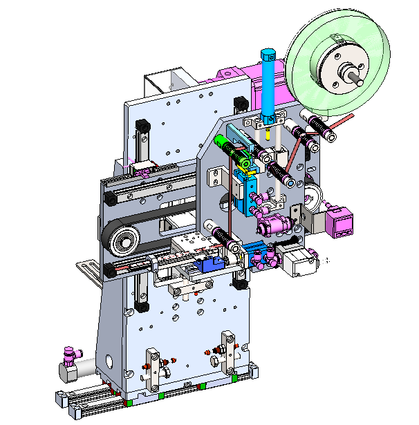
5.4 Separator Unwinding
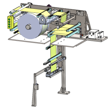
5.4.1 Function:
The full roll separator is unwound continuously with tension control, buffering, and edge correction. Coordinated with the electrode sheet transfer robot and the reciprocating motion of the stacking table, Z-fold stacking is completed.
5.4.2 Configuration and Parameters:
1. Utilizes a 3-inch single-axis air-expanding shaft unwinding system with a splicing platform and diameter calculation function; the splicing platform includes scale markings.
2. Tension mechanism uses a cylinder with a swing arm; tension range: 0–2000gf. The buffering roller is controlled by a cylinder and precision regulator to ensure quick response during separator switching and prevent roll-off.
3. Carbon fiber rollers, polished to Ra0.8+, prevent separator wrinkling.
4. Edge correction uses a high-sensitivity fiber optic sensor from Japan, detecting all types of separators regardless of transparency. A servo motor with precision screw executes correction with ±0.1mm precision, correction stroke: ±15mm.
5. Separator loading is aligned with the inner reference edge, mechanical positioning makes roll change convenient; max roll diameter: ≤Φ350mm.
6. Includes diameter calculation; auto alarm and stop when material is low.
7. Static eliminator installed near the stacking table prevents dust attraction and contamination.
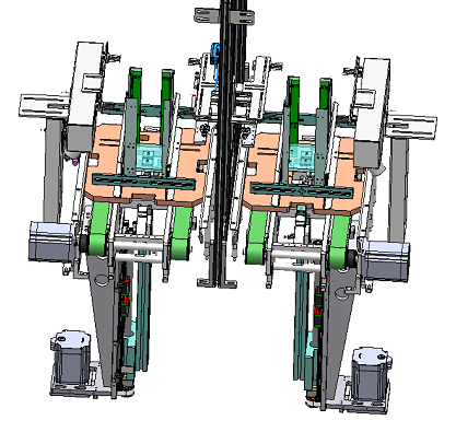
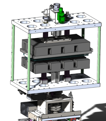
5.5 Stacking Table Assembly
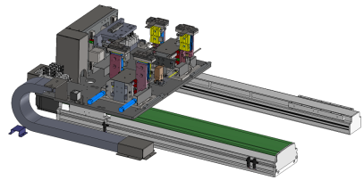
5.5.1 Function:
The electrode transfer robot places sheets into the stacking table. Pressing blades alternate to compress the sheets while the table switches between cathode and anode positions, completing Z-fold stacking.
5.5.2 Configuration and Parameters:
1. Servo motor + precision ball screw enable lifting with ±0.01mm precision; stacking height 10–30mm, stack count shown in real time on the HMI.
2. Pressing blades move forward/backward via cylinder; made of SUS440C high-hardness material (HRC > 50°) with arc transitions and mirror polish. Pressure adjustable by precision regulator; no sheet damage, powder drop, or separator wrinkling. Long-term use without deformation.
3. Horizontal movement by servo motor + precision ball screw, offering high responsiveness, speed, and accuracy; positioning precision: ±0.02mm.
4. Uses 4 sets of pressing blades to alternately hold sheets in place; ensures no misalignment or damage during Z-fold stacking.
5.6 Separator Cutting Mechanism
5.6.1 Function:
Uses thermal cutting; a heating element rapidly heats to cut the separator after stacking.
5.6.2 Configuration and Parameters:
1. Powered by cylinder; fast-heating thermal element, suitable for both normal and ceramic-coated separators. Equipped with a safety guard. Cut edges are free of cracks, curling, burrs, frays.
2. Cutter lifespan: ≥100,000 cycles.
3. Cuts flush with cell edge or extends 1–2mm beyond table edge.
4. Cutting straightness: ±0.3/300mm.
5.7 Stacking Discharge Clamp
5.7.1 Function:
Transfers finished cells from the stacking table to the separator cutting, tail winding, and taping station.
5.7.2 Configuration and Parameters:
1. Uses thin-type parallel air gripper with adjustable design to fit varying cell thickness/width; easy format changeover.
2. Pressure regulated by precision pressure valve; non-metallic surfaces to prevent scratches.
3. Gripper includes positive air blow to prevent bottom separator sagging and wrinkling.
4. Horizontal movement via servo + timing belt, fast response, accurate positioning: ±0.05mm.
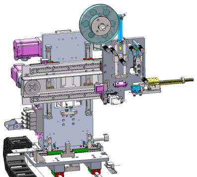
5.8 QR Code Labeling Mechanism
5.8.1 Function:
Automatically pulls, cuts, scans, and applies QR-coded tape to the cell surface. Automatically rejects defective QR codes.
5.8.2 Configuration and Parameters:
1. Pulling by servo + timing belt, cutting via cylinder. Taping length/position precision: ±0.5mm. Tape width: 10–30mm.
2. Cutter made of SKH-9 high-speed steel, HRC > 50°, lifespan ≥200,000 cycles.
3. Pre-scan QR code before taping; defective codes are automatically discarded.
4. Uses quick-release chuck for easy roll replacement; inner diameter: 3 inch, max diameter: ≤Φ150mm. Alarm when tape runs out.
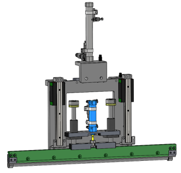
5.9 Adhesive Clamp Mechanism
5.9.1 Function:
Clamps the cell with upper and lower plates, by side adhesive application.
5.9.2 Configuration and Parameters:
1. Clamps the cell tightly to ensure clean and secure adhesive application.
2. Clamp pressure regulated by precision pressure valve.
3. Clamp contact surface is non-metallic to avoid cell damage.
4. Clamp rotation driven by servo + precision reducer, includes mechanical pin positioning for accurate tape placement.
5. Horizontal movement via servo + timing belt, fast and accurate; positioning precision: ±0.05mm.
5.10 Side Tape Application Unit
5.10.1 Function:
This unit uses C-type taping, applying tape from bottom to top on the cell clamped in the adhesive fixture. It performs automatic tape pulling, cutting, and application around the four sides. The taped cell remains neat, firm, and undamaged on electrodes, tabs, or separator.
5.10.2 Configuration and Parameters:
1. After the cell is clamped by the tape fixture, it is moved to the taping unit. C-type taping is performed from bottom to top with automatic tape feeding, pulling, and cutting. The roller and tape feeding mechanisms are treated for anti-stick. The taped cell is neat, tight, and damage-free.
2. Z-axis and X-axis are driven by servo motor and synchronous belt, tape length and position accuracy ±0.5mm. Pulling length is adjustable from 20–60mm, tape width 10–30mm.
3. After taping, a cylinder pushes the tape cutter to cut the tape. Four-sided taping is supported; tape position and count can be set via touch screen and saved for future use.
4. Cutter is made of high-speed mold steel SKH-9, HRC50°+, sharp and consistent cutting, lifetime ≥200,000 times.
5. Quick-release chuck design for easy tape replacement; inner diameter 3 inches, max roll diameter ≤150mm, low tape alarm.
5.11 Cell Unloading Manipulator
5.11.1 Function:
The manipulator unloads the heat-pressed cells, transfers them to the tray without scratching the separator or damaging the cells.
5.11.2 Configuration and Parameters:
1. Clamp jaws driven by cylinders for fast response and precise positioning.
2. Jaws clamp the cell securely; pressure is adjustable via precision regulator to avoid cell surface damage.
3. After gripping the cell, it is placed into the tray, which then automatically opens. The tray is transferred via conveyor line.
5.12 Dust Removal System
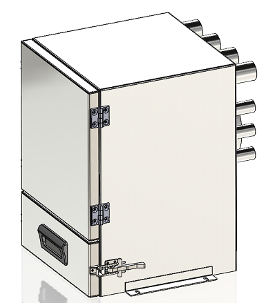
5.12.1 Function:
Configured with dust removal fan, connected to each station through pipelines. Negative pressure suction collects dust into the dust box. The equipment top is equipped with FFU clean air system to ensure positive pressure and cleanliness ≥100,000 class.
5.12.2 Configuration and Parameters:
1. Full-process dust control during die-cutting. Equipped with ionizing air dust removal on both sides of electrode sheets, and circular strong magnets with magnetic field >8000Gs.
2. Suction method: centrifugal fan connected to dust box; airflow ≥15m/s.
3. FFU filter units on the top deliver clean air into machine. With vacuum extractor, air circulates effectively.
4. Internal cleanliness ≥100,000 class.
5.13 Machine Frame and Enclosure
5.13.1 Function:
The frame is welded with square tubing and coated with paint. The enclosure combines aluminum profiles and acrylic panels for functional area separation and protection.
5.13.2 Configuration and Parameters:
1. Welded square tube frame with painted surface. Color as per client’s swatch.
2. Shielded with sheet metal/aluminum alloy + acrylic panels.
3. Sensor-equipped maintenance doors with interlocks prevent accidents.
4. Sealed structure with safety switch and emergency stop button.
5.14 Operation System (Data Management System)
5.14.1 Function:
Control operation of each unit via touch screen interface.
5.14.2 Configuration and Parameters:
1. PLC-based system; touch screen and button operation.
2. User-friendly touch screen, adjustable parameters, interlock protection.
3. Data upload to MES; supports download of process parameters from MES. Manufacturer provides data interface as required.
4. Comprehensive fault alarm system; fault locations and component malfunctions displayed on the touch screen. Full I/O display.
5. Smooth operations with full alarm and anti-misoperation functions. Faults are shown clearly for quick troubleshooting.
6. Parameter settings are access-controlled. Password required for critical settings. At least two product parameter sets can be saved and recalled.
7. Four-level access control (admin, equipment, process, operator); auto logout after 3 mins of inactivity.
6. Equipment Energy Requirements
|
Item |
Specification |
|
Dimensions |
L4800 x W2400 x H2500 (subject to actual model) |
|
Weight / Load |
Approx. 5000Kg; >600Kg/m² |
|
Color |
As per customer-supplied color sample |
|
Power Supply |
AC380V 3-phase; Voltage fluctuation ±8% |
|
Power |
45KW |
|
Compressed Air |
0.5–0.7Mpa (5–7kgf/cm²), consumption 45m³/h |
|
Vacuum |
Built-in vacuum system |
|
Ambient Temp. |
5–40℃ |
|
Humidity |
5–55%RH |
|
Air / Dust |
No salty, toxic or corrosive gases; free of conductive dust |
|
Magnetic Field & Vibration |
No magnetic interference; free of impact or perceptible vibration |
7. Key Components and Consumables Configuration Table
7.1 Equipment Components Overview
|
No. |
Name |
Brand or Equivalent |
Remarks |
|
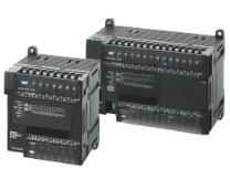
1 |
PLC Controller |
Siemens |
|
|
2 |
Servo Motor |
Siemens |
|
|
3 |
Stepper Motor |
Oriental, Shinano, Leadshine |
|
|
4 |
Pneumatic Components |
SMC, Airtac, CKD, CHELIC |
|
|
5 |
Magnetic Switch |
SMC, Airtac, CKD |
|
|
6 |
Solenoid Valve |
SMC, Airtac |
|
|
7 |
Ball Screw |
THK, MISUMI, TBI, HIWIN |
|
|
8 |
Linear Guide |
HIWIN, CSK, MISUMI |
|
|
9 |
Industrial Computer |
Adlink, Advantech |
|
|
10 |
CCD Vision System |
Supersonic, Hikvision, OPT |
|
|
11 |
Bearing |
NSK, SKF, MISUMI |
|
|
12 |
Dust Collector |
Puhua, Huele or equivalent |
|
|
13 |
Sensor |
Panasonic |
|
|
14 |
Fiber Optic Sensor |
Panasonic |
|
|
15 |
Reducer |
Xinliyin, Zhongda |
|
|
16 |
EPC Controller |
Boxing, Timac |
|
|
17 |
Touchscreen |
Weintek, Fuji, Proface, Kunlun Tongtai |
|
|
18 |
Relay |
Omron, Siemens, Schneider |
|
|
19 |
Power Supply |
Siemens, Omron, Schneider, Meanwell |
|
|
20 |
Circuit Breaker |
Schneider, Siemens, ABB or equivalent |
|
|
21 |
Photoelectric Switch |
Omron, SICK, Keyence or equivalent |
|
|
22 |
Vacuum Pump |
Leybold, Aodopao, Zhongde |
|
|
23 |
Tension Controller |
MESSSYS, Boxing, Timac, Kaiduo |
|
|
24 |
Contactor |
Schneider, Siemens, ABB or equivalent |
|
|
25 |
Electronic Scale |
AND, Mettler, Hongweicheng |
|
|
26 |
Timing Pulley / Belt |
IHD, MISUMI or equivalent |
|
|
27 |
Barcode Scanner |
Keyence, Honeywell |
|
7.2 Consumables Overview
|
No. |
Name |
Model / Spec |
Manufacturer |
Remarks |
|
1 |
Dust Filter Cartridge |
/ |
LITH |
For fan |
|
2 |
Separator Cutter |
Customized |
LITH |
|
|
3 |
Side Tape Cutter |
Customized |
LITH |
|
|
4 |
Inner Suction Cup |
PAG-15 |
Market / Domestic |
|
|
5 |
Outer Suction Cup |
X7H-1070BC |
Market / Domestic |
|
7.3 Spare Parts Included (per unit)
|
No. |
Name |
Model / Spec |
Qty |
Manufacturer |
Remarks |
|
1 |
Photoelectric Switch |
FC-SPX303Z |
2 |
Jiazun / Domestic |
|
|
2 |
Magnetic Switch |
DMSG-20 |
2 |
Airtac / Taiwan |
|
|
3 |
Suction Rod |
X7H-1070BC |
10 |
Market / Domestic |
|
|
4 |
Suction Cup |
PAG-15 |
10 |
Market / Domestic |
|
|
5 |
Solenoid Valve |
SY5120-5LZD-01 |
2 |
SMC / Japan |
|
|
6 |
Side Tape Cutter |
/ |
1 |
Customized |
|
|
7 |
Separator Cutter |
/ |
1 |
Customized |
|
|
8 |
Hex Wrench Set |
1.5-10MM (9 pcs) |
1 |
EIGHT / Japan |
|
|
9 |
Open-End Wrench Set |
8 pcs |
1 |
SATA / USA |
|
|
10 |
Strong Magnet Screwdriver (Flat) |
DG-03 |
1 |
ENGINEER / Japan |
|
|
11 |
Strong Magnet Screwdriver (Philips) |
DG-04 |
1 |
ENGINEER / Japan |
|
|
12 |
Needle Nose Pliers |
RML-150 / 6 inch 150mm |
1 |
RUBICON / Japan |
|
|
13 |
Diagonal Pliers |
RD-150 / 6 inch 150mm |
1 |
RUBICON / Japan |
|
|
14 |
Flat-nose Pliers |
8 inch |
1 |
RUBICON / Japan |
|
|
15 |
Toolbox |
Metal, 2-layer 300x200x200 |
1 |
Market / Domestic |
|
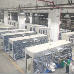
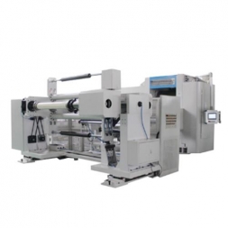
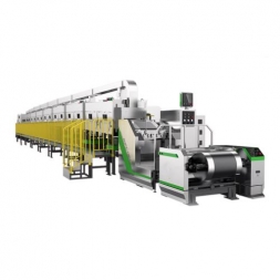
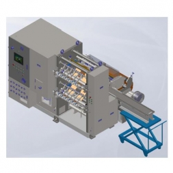
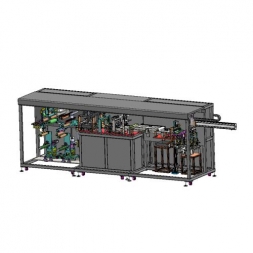
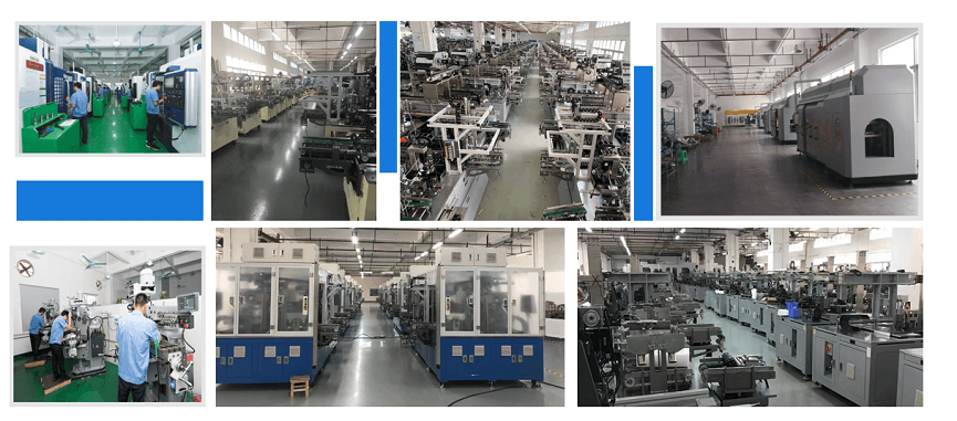
Production Assembly Plant
![]()

![]()
![]()

![]()
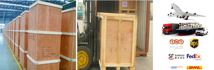
1 Standard exported package: Internal anticollision protection, external export wooden box packaging.
2 Shipping by express, by air, by sea according to customers' requirements to find the most suitable way.
3 Responsible for the damage during the shipping process, will change the damaged part for you for free.
DELIVERY TIME:15-20 days after confirming the order, detail delivery date should be decided according to
production season and order quantity.

 Subscribe to us
 ONLINE
 +86 13174506016
 Louis@lithmachine.com
 +86 18559646958
 18659217588