ItemNo :
LITH-J600D-BGMOQ :
1Compliance:
Warranty:
Delivery Time:
5 days
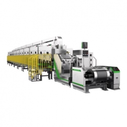
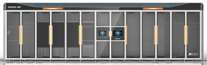
Automatic Die Cutting Machine for Lithium-Ion Battery Cathode and Anode Sheets
1.1 Equipment Function Overview:
This equipment is primarily used for the forming of cathode and anode electrode sheets in the stacking process of power lithium-ion batteries (continuous coating process).
The electrode roll is installed onto the unwinding air-expansion shaft of the equipment by AGV or manually. The equipment automatically unwinds the roll, and the web guiding mechanism performs automatic web alignment correction during the unwinding process. The tension control system controls the unwinding tension. Before entering the laser cutting process, a secondary web alignment correction (process correction) is performed. The electrode sheet is then subjected to air knife dust removal, tension control, sheet buffering, CCD defect inspection, and the V-notch punching station uses a hardware mold to punch the V-shaped notch.
After that, the pulling mechanism transports the material to the cutting position to cut into sheets. The sheets are then transported via a conveyor belt to the dimension inspection station. After powder brushing inspection (both sides), defective products are automatically rejected into the NG material box, while qualified products are collected into the finished product material box.
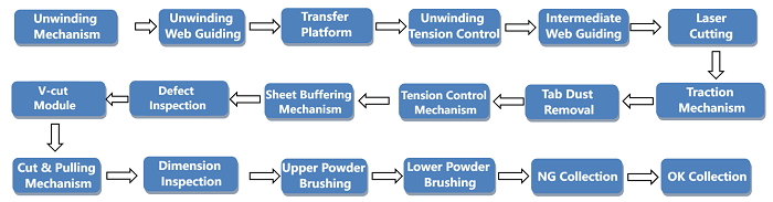
1.2 Action Flow:
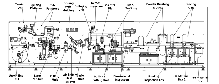
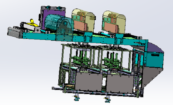
1.3 Equipment Diagram (Single Unwinding):
Equipment Dimensions (L×W×H): 9000 × 2500 × 2800 mm
1.4 Equipment Features:
1. Single-roll unwinding mechanism: Each shaft can load a roll with a maximum diameter of 650 mm. The air-expansion shaft adopts a special design to reduce friction between the roll and the shaft, making it labor-saving and time-saving, with quick and easy material changeover. Automatic unwinding is driven by a servo motor and controlled by a program. The unwinding diameter algorithm calculates changes in the roll diameter to determine whether the electrode sheet roll is nearly depleted. When the roll is finished, the machine emits an alarm signal and stops automatically.
2. Pulling mechanism: Uses a patented servo pulling mechanism, pulling accuracy ±0.2 mm.
3. Buffering mechanism: Uses servo + module drive combined with tension buffering to ensure continuous unwinding without stopping during die cutting, improving production efficiency and ensuring pulling accuracy.
4. Electrode sheet cutting knife: Uses a patented cutting mechanism with low dust generation and minimal burrs. The cutting knife position can be adjusted via servo drive according to the sheet size, improving width accuracy of the electrode sheet.
5. Integrated functions: This machine can integrate CCD inspection and powder brushing functions to improve overall utilization rate.
6. Patented dust removal method: Reduces secondary dust contamination and effectively avoids damage to electrode sheets caused by brushing.
7. Laser die-cutting for tabs: Greatly reduces the forming cost of electrode sheets.
8. Automatic cutter avoidance for adhesive tape: When encountering adhesive tape, the cutter automatically avoids it, reducing mold and cutter damage.
9. Neat sheet stacking: Servo punching mode ensures sheet stacking neatness ±1 mm.
10. Dust control by equipment zones: The equipment is equipped with an internal high-efficiency FFU filtration system to ensure that the dust level inside the equipment reaches Class 100,000.
11. MES communication function: Two network ports reserved.
2.1 Applicable Incoming Material Dimensions and Specifications
|
No. |
Item |
Parameter |
|
1 |
Incoming material width |
200–600 mm (including tabs) |
|
2 |
Incoming material thickness |
60–300 μm |
|
3 |
Inner diameter of incoming material roll |
3 inches |
|
4 |
Outer diameter / weight of electrode roll |
≤ 650 mm / ≤ 500 kg |
|
5 |
Coating method and tab damage requirement |
Continuous coating, single-side tab, tab damage less than 0.5 mm |
|
6 |
Winding alignment tolerance of incoming material |
≤ ±3 mm |
|
7 |
Wave edge height of incoming material |
≤ 0.5 mm |
|
8 |
Coating width tolerance of incoming material |
≤ ±0.5 mm |
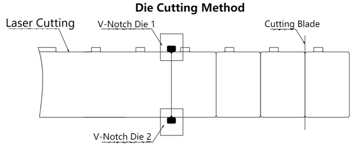
2.2 Electrode Sheet Die-Cutting Method
2.3 Customer Product Dimension Confirmation Table
|
Model |
Cathode Size |
Anode Size |
Tab Size |
Tab Pitch |
Corner Radius R |
||
|
Length(B) |
Width (A) |
Length(B) |
Width (A) |
||||
|
|
|
|
|
|
|
|
3 |
|
|
|
|
|
|
|
|
3 |
|
|
|
|
|
|
|
|
3 |
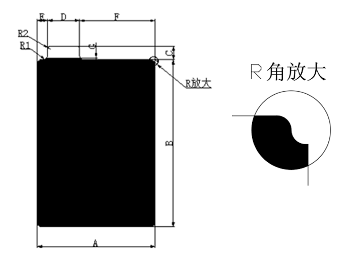
2.4 Electrode Sheet Burr
l (Metal die) Flat burr – Vk (metal burr) ≤ 10 μm
l (Metal die) Vertical burr – Vh (metal burr) ≤ 15 μm
l (Laser) Flat burr – Vk (metal burr) ≤ 15 μm
l (Laser) Vertical burr – Vh (metal burr) ≤ 18 μm
|
No. |
Item |
Parameter |
Remarks |
|
1 |
Electrode sheet length |
200–600 mm (including tab) |
|
|
2 |
Electrode sheet width |
80–265 mm |
|
|
3 |
Inner diameter of feeding roll |
3 inches |
|
|
4 |
Outer diameter of feeding roll |
≤ 650 mm (single roll) |
|
|
5 |
Equipment production speed |
Width (80–120 mm) ≥ 120 PPM Width (120–180 mm) ≥ 90 PPM Width (180–265 mm) ≥ 60 PPM |
Benchmark |
|
6 |
Electrode sheet dimensional accuracy |
±0.2 mm |
|
|
7 |
Melting bead |
≤ 10 μm |
|
|
8 |
Heat-affected zone |
≤ 120 μm |
|
|
9 |
Metal exposure |
≤ 50 μm |
|
|
10 |
Cutter lifespan |
After each regrinding, ≥ 1 million cycles Total lifespan ≥ 10 million cycles (with ≥ 10 regrindings) |
|
|
11 |
Collection alignment in material box |
±0.5 mm |
|
|
12 |
Equipment noise |
≤ 75 dB (measured at 1 m from the machine) |
|
|
13 |
Dimensional CCD inspection |
Accuracy ±0.15 mm |
|
|
14 |
Defect CCD inspection |
Missed detection: 0 False detection ≤ 0.5% |
Depending on incoming material |
|
15 |
Power supply |
AC 380V ±5%, three-phase, 50 Hz Starting power ≤ 50 kW Running power ≤ 35 kW |
|
|
16 |
Air supply |
Compressed air 0.5–0.6 MPa Air consumption: 800 L/min |
|
|
17 |
Equipment dimensions |
Approx. 9000 × 2500 × 2800 mm (main body) |
|
|
18 |
Appearance color |
Standard warm gray 1C; if customer specifies, color sample must be provided |
|
|
19 |
Equipment weight |
Approx. 8000 kg |
|
|
20 |
Product yield rate |
≥ 99.8% |
|
|
21 |
Equipment failure rate |
≤ 1.5% |
|
|
22 |
Applicable ambient temperature |
0–50°C |
|
4.2.1 Unwinding Module
l The unwinding mechanism adopts one set of 3-inch air expansion shaft structure, with a maximum electrode roll diameter of φ650 mm.
l Unwinding direction can be clockwise or counterclockwise.
l During loading, a linear fiber optic sensor assists in positioning the electrode roll.
l The unwinding mechanism is equipped with a web guiding system, with guiding accuracy ≤±0.2 mm and guiding stroke ±50 mm.
4.2.2 Splicing Module
l Equipped with a roll splicing platform, with auxiliary marking lines for easy manual splicing.
l At the cutting position, a dust collection box is installed to collect and clean dust via negative pressure suction.
4.2.3 Tension Module
l Swing roller speed synchronization control; potentiometer detects signals and sends to PLC, PLC controls servo motor speed.
l PLC + low-friction cylinder + electric proportional valve adjust tension.
l Tension range 10–150 N, with stable running tension fluctuation ≤5%.
4.2.4 Process Web Guiding
l Uses a web guiding module with high accuracy and simple operation. Manual correction compensation can be done via module buttons to ensure overall unwinding accuracy.
l Process web guiding accuracy ≤±0.1 mm, guiding stroke ±20 mm.
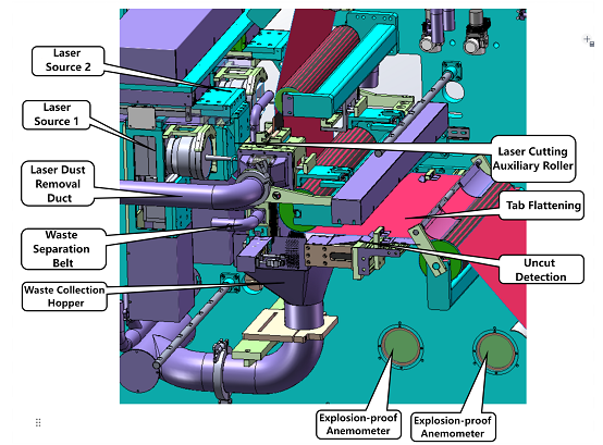
4.2.5 Laser Die-Cutting Module
1. 250 W fiber laser, adjustable pulse width, laser power stability <5%.
2. Laser focal length adjustment accuracy ±0.01 mm.
3. Galvanometer repeat positioning accuracy ±0.02 mm.
4. Minimum cutting radius R ≥ 1.
5. Dual-station laser cutting system.
6. Cutting dimensions are accurate without sticking; both tab side and non-tab side are equipped with uncut and missed-cut detection sensors.
7. During electrode sheet unwinding, detects incoming defects, including incoming tape and in-machine splicing; upon detecting tape, the system can be set to normal cutting or skip cutting; after skipping, the first tab position and splice spacing can be set to improve material utilization.
8. Entire cutting area enclosed in a semi-sealed dust removal cover; laser cutting area has an independent secondary sealed structure; dust generated during cutting is removed directly by a negative pressure dust collector; designed air velocity ≥20–25 m/s (adjustable) with real-time monitoring.
9. Laser protection: observation window of the laser cutting chamber uses laser protective panel.
10. Waste from laser cutting is collected by a compactor; waste passes through waste pipeline into the compactor without affecting continuous cutting.
11. Dust collection ducts within 1 m of laser cutting position use metal pipes; non-metal pipes use flame-retardant materials.
12. Laser cutting control system supports both equal-spacing and non-equal-spacing modes, with free switching and parameter setting.
13. Uses PSO control technology to precisely control single-point energy output at the specified position; laser frequency control prevents overcutting or incomplete cutting, effectively controlling burrs and heat-affected zone.
4.2.6 Buffering Module
l Uses servo + precision ball screw drive combined with tension control buffering, ensuring continuous unwinding during die cutting, improving production efficiency, maintaining stable tension, and ensuring pulling accuracy.
l Rollers are lightweight to reduce inertia, improving pulling accuracy and equipment stability.
l Over-rollers are made of carbon fiber.
l Control method adopts electronic cam overlay control.
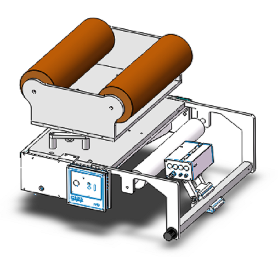
4.2.7 V-Notch Punching Module
l Uses two sets of V-notch punching to form tabs.
l Punching module has automatic web guiding; sensors detect electrode sheet position and adjust die position in real time to ensure consistent punching height. Two color mark sensors detect tape on the front side for skip cutting.
l Equipped with safety light curtain; if triggered during operation, equipment stops immediately to prevent accidents.
l Die base plate is made of marble for improved flatness, ensuring no deformation after installation; flatness ≤0.01 mm.
l Quick positioning between die and base plate for easy disassembly; changeover time ≤0.5 hours.
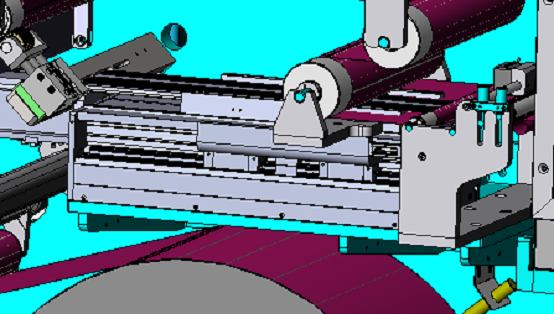
4.2.8 Pulling Module
l Patented servo pulling mechanism, maximum pulling speed 60 m/min, pulling accuracy ±0.2 mm.
l Pulling roller uses EPDM material; during normal operation, no surface dust or particle accumulation, ensuring sheet surface smoothness without dents.
l Upper pulling roller rubber-coated with hardness 90°, ensuring close contact with lower roller.
l Lower pulling roller is hard chrome-plated HV750 steel roller, precision ground and polished, surface roughness Ra0.2.
l Upper roller pressed by cylinder to ensure dimensional accuracy.
l Cutter drive mode: servo motor drive + cam mechanism.
l Blade: imported G5 tungsten steel.
l Blade change time ≤0.5 hours.
4.2.9 Conveyor Belt Module
A. Upper Belt:
l Driven by servo motor; motion curve controlled by constant acceleration/deceleration electronic cam for smoothest movement and minimal impact.
l Belt has 3 mm holes; negative pressure through belt holes to hold electrode sheets.
l Automatic brush cleaning; belt made from 1.5 mm PU top + PVC base special material.
l Integrated with CCD dimensional inspection and top surface dust removal.
B. Lower Belt:
l Driven by servo motor; motion curve controlled by constant acceleration/deceleration electronic cam for smoothest movement and minimal impact.
l 1.5 mm belt with 3 mm holes, divided into multiple strips; negative pressure through belt holes to hold sheets.
l Automatic brush cleaning; belt made from PU top + PVC base special material.
l Integrated with electrode sheet unloading and bottom surface dust removal.
4.2.10 Powder Brushing Module
l Performs powder brushing and cleaning of the electrode sheet surface to promptly remove waste and dust generated during punching.
l Dust is filtered through a dust collection and filtration system to prevent diffusion to the surrounding area.
l Dust removal system noise: ≤75 dB.
l Cleaning device adopts centralized dust collection.
l Strong dust removal mechanism combining ion air blowing and suction.
l Powder brushing module is equipped with a 10,000 G strong magnet to remove magnetic dust.
l Dust removal at unwinding section by suction to clean sheet surface.
l Dust generated during die cutting removed through lower hollow section with negative pressure suction.
l Dust generated under cutter removed by suction.
l Brushes clean stubborn dust from the sheet surface.
4.2.11 Electrode Sheet Collection Device
l Sheets are automatically collected into the material box via conveyor belt; the box has automatic lifting and full-material alarm.
l Equipped with electrode sheet buffering mechanism.
l After punching, sheets are stacked in the box without collision to edges.
l Stacking accuracy: ≤±1 mm; sheets do not contact box edges during dropping.
l Sheet discharge method: conveyor belt discharge with vacuum adsorption conveying.
l Stacking height control: stepper motor controls sheet quantity.
l Forced emergency stop button installed in the discharge area.
l Automatic rejection of defective sheets; alarm for 3 consecutive defective sheets, stop for 5 consecutive defective sheets, plus other anti-misfeed designs.
4.2.12 Defect Inspection
l As sheets pass over the roller, a linear array camera scans the sheet surface line by line, stitching into a complete image.
l Specific image detection algorithms analyze and calculate features; based on preset defect parameters, the software outputs pass/fail signal, and defective sheets are automatically rejected.
l Uses two 8K line-scan black-and-white high-speed industrial cameras and a 600 mm effective-length high-brightness linear light source; can inspect sheets up to 600 mm wide.
l CCD monitors both sides of the sheet, exporting all defect data to CSV file.
l Inspection standard parameters (subject to actual process): Miss detection = 0, false detection ≤0.5%, grayscale difference ≥30.
l AI-based defect recognition and product classification.
|
Defect Type |
Rejection Threshold |
|
|
Bright spot |
> 0.5 mm² |
|
|
Foil exposure |
> 0.5 mm² |
|
|
Tape joint |
> 20 mm length, >1 mm width |
|
|
Scratch |
>10 mm length, >0.5 mm width |
|
|
Crack |
> 0.5 mm² |
|
|
Hard particle |
> 0.5 mm² |
|
|
Fish scale (pinhole) |
> 0.5 mm² |
|
|
Powder drop |
> 0.5 mm² |
|
|
Rolling adhesion |
> 0.5 mm² |
|
|
Dried spot, black dot |
> 0.5 mm² |
|
|
Dark spot |
> 0.5 mm² |
|
|
Wrinkle / bent corner |
> 2 mm |
|
|
Edge foil exposure |
> 0.5 mm² |
|
|
Hole |
Radius > 1 mm or >20 pixels |
|
4.2.13 CCD Dimensional Inspection Module
l CCD captures images to inspect tab strip height and exposed foil; can measure sheet length, tab-to-edge distance, tab width, and sheet angle.
l Inspection accuracy: ±0.1 mm; Miss detection = 0, false detection ≤3‰.
l Uses area-scan industrial camera.
l Uses backlight detection to improve inspection accuracy.
l Before inspection, a pressing mechanism flattens the sheet to prevent errors due to poor adsorption.
l Inspection items include: sheet width, height, angle, tab shoulder width, and tab strip.
4.2.14 Control System
l Composed of 1 PLC, one 15-inch touch screen, and other electrical components.
l Uses bus-type connection to reduce cable quantity; electrical cabinet wiring is neat and aesthetic.
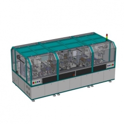
4.2.15 Machine Frame and Enclosure
l Frame is welded from high-strength square steel tubing, with painted surface.
l Equipped with dustproof enclosure made of aluminum alloy or sheet metal and acrylic panels.
l Top of enclosure fitted with FFU filtration unit delivering air into the machine; combined with vacuum dust collection for internal air circulation.
l Cleanliness inside enclosure: Class 100,000 or better.
5.1 Main Components List:
|
No. |
Main Configuration |
Brand |
Origin |
|
1 |
PLC control system |
Trio |
UK |
|
2 |
Web guiding |
Puliyuan / Bat |
China |
|
3 |
Touch screen |
Weilen |
China |
|
4 |
Servo motor |
Estun |
China |
|
5 |
Tension controller |
Fujikura |
Japan |
|
6 |
Pneumatic components |
SMC, Airtac |
Japan, Taiwan |
|
7 |
Ball screw & guide rail |
Hiwin |
Taiwan |
|
8 |
Bearing |
NSK |
Japan |
|
9 |
Switchgear |
Schneider, Panasonic |
Germany, Japan |
|
10 |
Photoelectric sensor |
Omron, Panasonic, Baumer, Julong |
Japan, China |
|
11 |
CCD |
Hikvision |
China |
|
12 |
Laser source |
IPG |
Germany |
5.2 Consumable Parts List:
|
No. |
Name |
Specification |
Remarks |
|
1 |
Photoelectric switch |
EE-SX671A |
Omron |
|
2 |
Intermediate relay |
MY2J-12VDC |
Schneider |
|
3 |
Pushbutton switch |
φ22 |
Schneider |
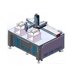
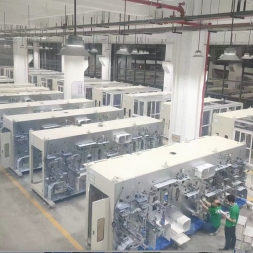
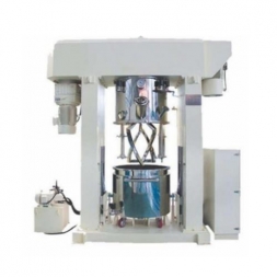
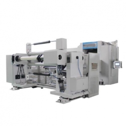
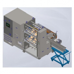
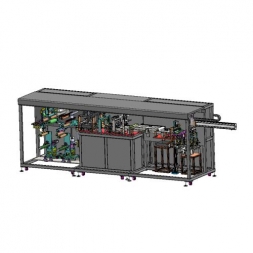
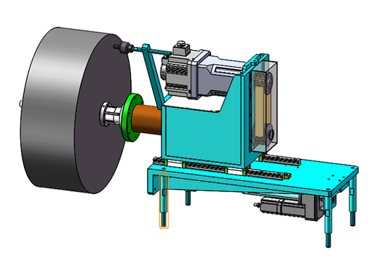
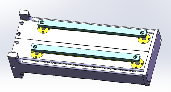
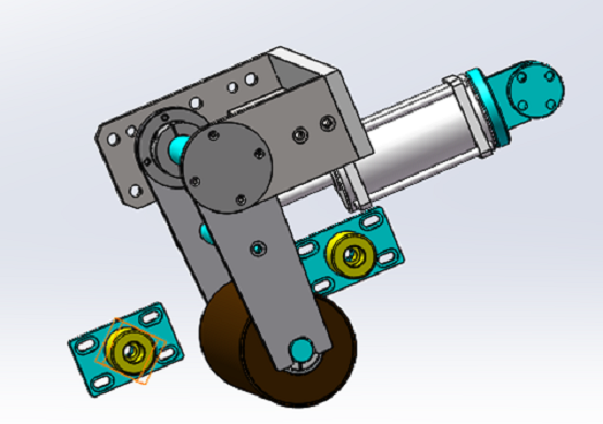
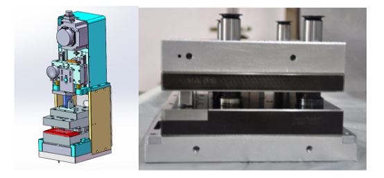
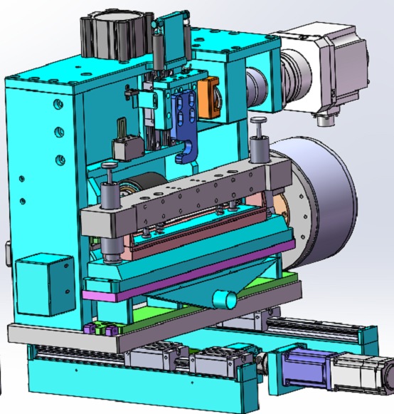
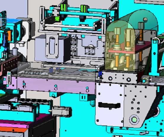
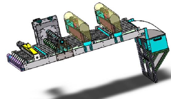
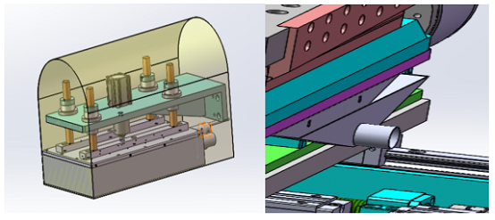
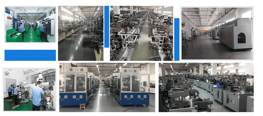
Production Assembly Plant
![]()
![]()
![]()

![]()
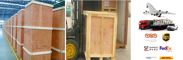
PACKAGE:
1 Standard exported package: Internal anticollision protection, external export wooden box packaging.
2 Shipping by express, by air, by sea according to customers' requirements to find the most suitable way.
3 Responsible for the damage during the shipping process, will change the damaged part for you for free.
DELIVERY TIME:15-20 days after confirming the order, detail delivery date should be decided according to
production season and order quantity.

 Subscribe to us
 ONLINE
 +86 13174506016
 Louis@lithmachine.com
 +8618659217588
 18659217588